EFI For Big Blue


|
...and by the way, that harness is set to arrive today. Looking forward to getting it.
Steven A. Gauvry - 1985 F150 5.0 EFI
|
|
Administrator
|
This post was updated on .
Steve - Ray is a wonderful help, isn't he!
Ok, now that it appears that we have the wiring sorted, sorta, I've spent some time thinking through the interface from the 1990ish FDM sending units to the Bullnose fuel gauge. And, I think I have a plan that will work. It is based on an Arduino microcontroller, and probably an Uno since it only needs a source of power to work and has a USB connector for setup via a computer. The resistance for the sending unit in the fuel delivery module will be 22.5 ohms when the tank is empty and 145 ohms full. One end of the resistor is tied to ground, so there will have to be a resistor from the 5v supply on the Arduino to the potentiometer/sending unit, meaning the circuit will go from the 5v supply through a resistor and connect there to both the analog input of the Arduino as well as to the potentiometer. My calcs say that a 220 ohm pull up resistor will give .46v at empty and 1.99v at full, with a current flow of 21 and 14 milliamps respectively. The resistance of the heating coil in the gauge is 12 ohms, and the Bullnose sending unit runs from 10 ohms at full to 73 ohms at empty. That means with the 5.4v source we would have 250 milliamps of current at Full and 60 mills at Empty. But if the digital output of the Arduino is turned on as a replacement for the sending unit it would be sinking 5.4 volts through 12 ohms, giving 460 milliamps. So we need 60/450 or 14% duty cycle to generate enough heat to register Empty, and 250/450, or 55% to give Full. But that current is too much for the outputs of an Arduino, so we need another board (shield) to sink the current. Circuitar makes one called the MOSFET Nanoshield and it is $9.90. However, the Nano board probably doesn't fit the Uno, so I'll just need to find another one. In any event, shields plug into the Arduino (stack, actually) so no wiring is needed. Just connect the wire from the gauge to the screw terminal, connect the wire from the sending unit to an input pin, provide power, program it, and go. Now we need to create an equation that gives 14% at .46v input, and 55% at 1.99vv input. Assuming a straight line then we need y=mx+b, and an online calculator gives y = .27X +.02. Plugging .464v into that equation gives 14.5%, and plugging 4.984v in gives 55.6%. Plenty close enough since none of the components we are playing with are that precise. Further, the transistor used to sink the current won't take the voltage fully to zero. But we now have an equation and can tune the "m" and "b" parts of it as this is implemented. Thoughts? Drawings/schematics to make this clearer are in the works.
Gary, AKA "Gary fellow": Profile
Dad's: '81 F150 Ranger XLT 4x4: Down for restomod: Full-roller "stroked 351M" w/Trick Flow heads & intake, EEC-V SEFI/E4OD/3.50 gears w/Kevlar clutches
|
|
|
Bill - If you say so...
 I confess that what you've written is well beyond my understanding of electronics and so I'd be of no use to you at this time as far as sharing my ideas. However, I will take time trying to understand what you've written. By the way, Ray's harness just arrived. It is beautiful! What a gift!!! Steve
Steven A. Gauvry - 1985 F150 5.0 EFI
|
|
Administrator
|
Not that it will educate you on electronics, but here's what I'm talking about in a drawing format. The stuff in red is what I'd be adding.

Gary, AKA "Gary fellow": Profile
Dad's: '81 F150 Ranger XLT 4x4: Down for restomod: Full-roller "stroked 351M" w/Trick Flow heads & intake, EEC-V SEFI/E4OD/3.50 gears w/Kevlar clutches
|
|
|
This post was updated on .
OK. I understand the drawing. You're creating a digital input and output so you can get tank level readings. Did your truck originally come with digital readings, or are you configuring the Arduino to do analog readings? Or did you upgrade to digital gauges? If you performed an upgrade, what brand did you use?
Very cool in any case!
Steven A. Gauvry - 1985 F150 5.0 EFI
|
|
Administrator
|
Do you understand slang German? Jein. Yes and no.
 Actually, no Bullnose came with digital tank readouts. And that's not what I'm after. I'm just interfacing the later 1987+ sending unit with the Bullnose gauge. No one will ever know the Arduino is there as it'll tucked up under the dash where it can't be seen. (Unless I really do find other uses for it, as my nephew suggested.) The Bullnose gauges are really thermometers. Yes, really. There's a 12 ohm heating element in them and a bi-metal spring that moves the hand. As current flows through the heating element the spring unwinds and the hand moves up in the scale. And, since that is a slow process we can pulse the current to the resistor thousands of times a second and the gauge won't know it is getting hit with a pulsing signal. (In mathematics terms, the heat gets "integrated".) All of the pulses will be 5v in "height", but the trick is to control their width, meaning how long the pulse is. Or, in the parlance "Pulse Width Modulation" - PWM. So, that's what I'm going to do - control the width of the pulses so that the heat is exactly right to get the reading that reflects the amount of fuel in the tank. The Arduino will read the level by monitoring the voltage on the sending unit. Then it will calculate the correct duty cycle, meaning the "on" vs "off" time of the pulse, and send the pulses to the gauge's resistor. From my calculations the right duty cycle for Empty, which is different than no reading, is 14% on. And the duty cycle for Full is 55% on. But since I can plug a computer into the Arduino I can modify the equation, which is for a straight line: Y = MX + B. So, if I need to tweak either M or B I can so and see the results immediately. I'm sure that is "as clear as mud" as Dad would have said, but I'm pretty sure it will work. And, it gives us Bullnosers a way forward on the fuel systems. I'll happily share the code that I write, which will be very small, and the parts for the Arduino. Should be plug and play.
Gary, AKA "Gary fellow": Profile
Dad's: '81 F150 Ranger XLT 4x4: Down for restomod: Full-roller "stroked 351M" w/Trick Flow heads & intake, EEC-V SEFI/E4OD/3.50 gears w/Kevlar clutches
|
|
Administrator
|
Gary,
Is there some way to implement this in reverse? So that I can use my older senders with the gauge in the bricknose dash. BTW, my old senders read 16.5 -160 ish. The fact that the ohms are inverted had me scratching my head, along with the fact that due to the arc of the float arm the readings were non-linear. I guess this could work with a controller board rather than a processor. But my programming skills are nonexistent (IFTTT)
Jim,
Lil'Red is a '87 F250 HD, 4.10's, 1356 4x4, Zf-5, 3G, PMGR, Saginaw PS, desmogged with a Holley 80508 and Performer intake. Too much other stuff to mention. |
|
Administrator
|
Jim - I think the short answer is "Yes".
The 1987 EVTM shows your gauges are fed battery voltage and the sender just changes the resistance and, therefore, the current to ground. But an Arduino could be programmed to sink the same current, thereby playing like a resistor, depending on the input voltage from the Bullnose sender. However, it will still have to be PWM, but I think it can be so fast that the inertia of the movement will do the integration. The key will be in determining the equation. But do you really care to have "accuracy" in the middle of the range? We should be able to nail it at Full and Empty, but the easiest equation will be a straight line. However, if you could somehow measure the resistance as a function of the tank level then maybe we could come up with the equation. But, let's see if this works for me and then move on to yours? Do you like the approach?
Gary, AKA "Gary fellow": Profile
Dad's: '81 F150 Ranger XLT 4x4: Down for restomod: Full-roller "stroked 351M" w/Trick Flow heads & intake, EEC-V SEFI/E4OD/3.50 gears w/Kevlar clutches
|
|
Administrator
|
"MY" sender's are from '85-'86 bullnose, because they are the only two wire (non-pump) senders available with the bigger bung.
Just having the top and bottom quarter close to reality would be a vast improvement over below E when full and running empty at around 7/16. I zero the odometer and try to switch or refill when I get to 150 miles. The gauges seem almost like a stepper motor. I'm not sure how they are damped, or what kind of magnet returns them to zero. Maybe I could use a pot for the sink resistor and 'calibrate' the instrument that way?
Jim,
Lil'Red is a '87 F250 HD, 4.10's, 1356 4x4, Zf-5, 3G, PMGR, Saginaw PS, desmogged with a Holley 80508 and Performer intake. Too much other stuff to mention. |
|
Administrator
|
We can put a capacitor on the output of the Arduino/ground side of the meter. An electrolytic would damp it handily.
And we should be able to nail any two points on the scale. Maybe Empty and Full would work well enough for the area just above/below. But, if not, you could plug into the Arduino and change the M and B parameters. However, I'm not sure that I understand the "sink resistor". Do you mean what I've called the "pull up resistor" below? If so, you could put a pot there, but my concern is that it would confuse things. I think it is easier to play with M & B as it is easy and precise. Basically it would be the same system as I'm planning but w/o the ICVR, and since resistance values of the sender are different the pull up resistor would be different as well. 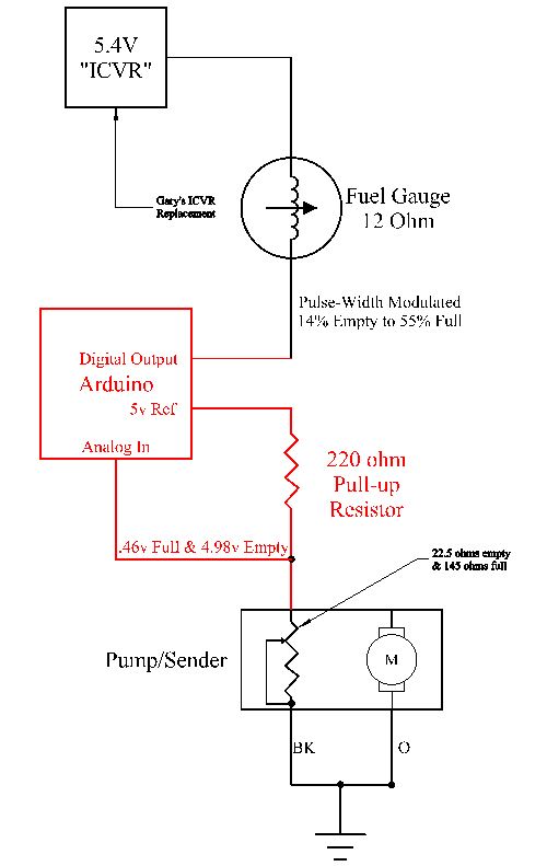
Gary, AKA "Gary fellow": Profile
Dad's: '81 F150 Ranger XLT 4x4: Down for restomod: Full-roller "stroked 351M" w/Trick Flow heads & intake, EEC-V SEFI/E4OD/3.50 gears w/Kevlar clutches
|
|
Administrator
|
Sorry, I didn't mean to hijack your thread.
Fixing my gauges is the least of my problems right now.
Jim,
Lil'Red is a '87 F250 HD, 4.10's, 1356 4x4, Zf-5, 3G, PMGR, Saginaw PS, desmogged with a Holley 80508 and Performer intake. Too much other stuff to mention. |
|
Administrator
|
In reply to this post by Gary Lewis
Gary, do you know the reason for Ford's 5.4V gauge circuit voltage? FWIW, the change to 12V was during the 1956 model year and it was obviously easier to add the ICVR then change all the gauges from chassis #xxxx on, since it worked fine, they used if for the next 31 years (1956-1986). The newer gauges are more like GM and Chrysler's older ones which would swing wildly on a partial tank, unlike Ford's which would gradually climb the longer they were on. If I had known there was a good solution to weird gauges, I might have kept my Tokyo by night instrument cluster in the convertible.
Bill AKA "LOBO" Profile
"Getting old is inevitable, growing up is optional" Darth Vader 1986 F350 460 converted to MAF/SEFI, E4OD 12X3 1/2 rear brakes, traction loc 3:55 gear, 160 amp 3G alternator Wife's 2011 Flex Limited Daily Driver 2009 Flex Limited with factory tow package Project car 1986 Chrysler LeBaron convertible 2.2L Turbo II, modified A413 |
|
Administrator
|
Jim - You aren't hijacking anything. Happy to think about other uses for the interface. In fact, I was just wondering about using it to drive the ammeter - as an ammeter. One issue we have with our ammeters is that the shunt doesn't know outflow from inflow, so the discharge scale has to be the same as the charge scale. But if we put a 3G alternator in then the capacity to charge has gone up to 90 to 160 amps while the discharge stays roughly the same. So, if we size the shunt to go full scale on the ammeter when charging you'll never see the ammeter move should the alternator fail.
What if we used an Arduino to move the ammeter and it monitored two different shunts? We could set the charge scale to fit the alternator, and the discharge scale could be set so that failure of the ammeter would get your attention. (And, we could light a warning light somewhere.) Bill - I was aware of why Ford did it. However, I'm not sure it is fair to say 5.4V. That's my number based on what it took to make three different Bullnose gauge setups work properly. You may remember, but I used the resistors that Ford recommended for calibrating gauges to come up with the voltage needed to make the gauges work correctly. And, 5.4 was it.
Gary, AKA "Gary fellow": Profile
Dad's: '81 F150 Ranger XLT 4x4: Down for restomod: Full-roller "stroked 351M" w/Trick Flow heads & intake, EEC-V SEFI/E4OD/3.50 gears w/Kevlar clutches
|
|
|
In reply to this post by 85lebaront2
Of course I'm going to throw my monkey wrench into the works and I apologize in advance for my technobabble.
The IVR in the early Ford trucks up to 1986 is not really a 5 volt regulator. It would be more accurately described as a pulse width power regulator. More simply, it is a flasher. It runs at approximately 1hz rate with about a 30 to 40% duty cycle. If you care to do a power calculation, 5 VDC contains about 42% of the power that 12VDC contains. The gauges are a movement that move the needle proportional to the current pulses flowing through the gauge. They react quite slowly, so you do not see the 1hz pulses on the needle. So, the gauge sender presents a variable current sink ranging from 70 ohms empty to 10 ohms full. The meter movement itself represents about 13 ohms by my measurement. When you do the math, the current through the meter becomes about 150 ma for empty to 500 ma for full. It is quite difficult to measure with an ammeter because of the pulsing supply voltage, (which has a peak voltage = to battery voltage). The later Ford FDM's have a resistance range from 16 ohms empty to 165 ohms full. I did a napkin sketch of what I feel would be a simple solution. Basically, I figured on using an NPN transistor as a current sink for the gauge. A 10 ohm resistor provides a limit to the current sink equal to the original 10 ohm reading from the 86 down sender. A 0.1 mf capacitor filters any noise out of the transistor. The 92 and up FDM sender is used as a variable voltage divider which will range from about 1V empty to about 5 volts full. This signal is applied to a resistor which drives the transistor B/E junction. The transistor will increase C/E current proportional to B/E current and I will assume a gain of 1000. This value may change depending on the actual gain of the transistor and must be of a value that allows the transistor to work in it's linear range. I figure 25K will be close, but I have not yet built a prototype. The best method to pick the value would be to select it for an accurate reading at "Full". An Arduino would be an interesting solution, but I think a single transistor would be far simpler. So, sorry if I bored anyone to tears, but this is what I used to do back in the previous millenium. 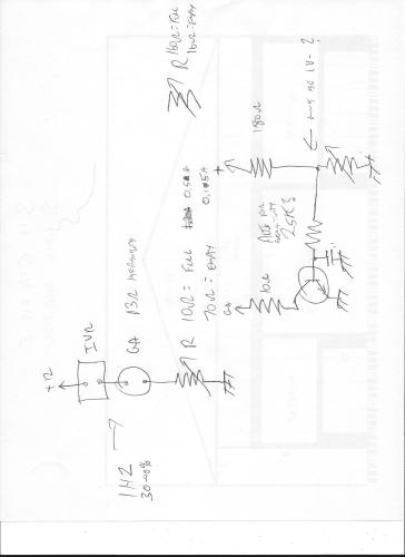
|
|
|
In reply to this post by sgauvry
Glad to help Steve.
|
|
|
In reply to this post by ArdWrknTrk
Jim,
Same circuit would work for bullnose senders with newer gauges. Would have to rework a few resistor values, but the circuit effectively reverses the slope of the sender resistance. By the way, resistance seems to be pretty linear to fuel tank float position. |
|
Administrator
|
In reply to this post by NotEnoughTrucks
Ray - That isn't a monkey wrench. It is an alternative. A monkey wrench would say my approach won't work. You didn't say that at all.
On the ICVR, do you remember my thread on FTE re ICVR Thoughts & Observations? I was able to measure things with a DVM as I installed a true voltage regulator in place of the "flasher" - and that is exactly the right term. So I had steady state and could measure it. Anyway, your solution will probably work great. I know how transistors work, but I don't understand the math so will have to assume you can nail it. However, I see the flexibility of the Arduino and, given my programming and math background, I am sure it'll be plenty accurate. And, changing parameters will be a piece of cake - as opposed to soldering in new resistors. 
Gary, AKA "Gary fellow": Profile
Dad's: '81 F150 Ranger XLT 4x4: Down for restomod: Full-roller "stroked 351M" w/Trick Flow heads & intake, EEC-V SEFI/E4OD/3.50 gears w/Kevlar clutches
|
|
|
Yup, that FTE thread sure nails the IVR. Before my time at FTE though, thanks for the link.
Possibly the best way to illustrate how that IVR works is with a test light. I do intend to breadboard my idea at some point. Problem is my component level days are way back there and a lot of my junkbox parts have disappeared over the years. Electronic component stores have gone the way of the dinosaur and I'm living in a small center. Nearest store is a 1 1/2 hour ride away and they don't stock much. Looks like Digikey or Mouser are the way to go today. Still, I think I could adapt a couple variable resistors to set full and empty scale. Becomes something of a balancing act using analog circuits like this, but they should be stable. Could have gone whole hog old school here and used vacuum tubes! Nah, bad idea. (German slang, "dumkopf") |
|
Administrator
|
I like the 'scope trace of the ICVR. Gross!
As for the light, I'm not sure that it wouldn't just be a blur if it is an incandescent light. Perhaps an LED would show something. I used to have a Heathkit powered breadboard and an open account at Digikey, but I gave the breadboard and all of my stock to my nephew - the one that I'm sure will mentor me on Arduinos. I'm all for buying it in, assembled, and getting on with things - although not for many months to come. But, if you can do it then GREAT!
Gary, AKA "Gary fellow": Profile
Dad's: '81 F150 Ranger XLT 4x4: Down for restomod: Full-roller "stroked 351M" w/Trick Flow heads & intake, EEC-V SEFI/E4OD/3.50 gears w/Kevlar clutches
|
|
Administrator
|
This post was updated on .
I already had the book Programming Arduino - Getting Started with Sketches and read again a large part of it last night. So today I wrote this "sketch", which is Arduino for "program". I am not saying it is perfect, but I think it is close, and it is all the programming that is needed to do the interface. I think it really is that simple.
Having said that, I'll put I/O to a USB-attached computer into the sketch to output the voltage reading taken in from the sending unit and the duty cycle to be written via PWM. That way it'll be easy to check to see what is going on. But I wanted you to see the simplicity of the sketch w/o the I/O, the base calculations. Anything after the two slashes (//) is a comment that will be ignored by the computer (compiler). But they are there for our edification. And note the two variables of "m" and "b". These are our knobs to twist in order to dial in the equation. int outputPin = 3; //Establishes an integer variable that is used for the output pin #
|
| Edit this page |