Fuel Injection upgrade


Administrator
|
I agree, I'd want to be able to see when it is time to clean the filter. And I'm not afraid of glass as it won't be hit with anything and I know it is stable.
Gary, AKA "Gary fellow": Profile
Dad's: '81 F150 Ranger XLT 4x4: Down for restomod: Full-roller "stroked 351M" w/Trick Flow heads & intake, EEC-V SEFI/E4OD/3.50 gears w/Kevlar clutches
|
|
|
Same here, I don't know why there aren't more quality options for a transparent filter for low pressure applications to make maintenance a bit easier. Spent a couple hours today working on wiring up my auxiliary fuse box. Got a lot of it done but still have a lot to do. The relay grounds I have not made up yet, I am waiting on a pack of an assortment of bare barrel terminals so I can bundle the ground wires together. I haven't decided which way I want to go; one option is to pair the grounds together so grounds for relays 3 and 4 pair together and grounds for relays 5 and 6 pair together and those two pair together. Another option is to find out the thread of the terminal on the inside of the fuse/relay box and make my grounds connect there with another eyelet ground going straight to battery ground. I also haven't finished wiring the fuses, I need to get more wiring to get some different colors to color code circuits as well as needing to figure out what thread pitch the ANL fuses are so I can figure out which fuses I want to bundle together. I'm thinking about having the lights/cb/dakota digital circuits on one main fuse and have the EFI circuits on another fuse and this will leave me with one ANL fuse to possibly fuse my 3G alternator with a 100A ANL fuse, but I am a little concerned about doing that for various reasons. On top of waiting for the bare barrel terminals I am also waiting on an assortment of marine x3 shrink tubing to seal the crimps within the fuse box. I also need to order a piece of plexiglass; my plan is to drill holes in the four corners for the box mounting legs to pass through so I can install small screws through the side of the box into the side of the plexiglass to hold the two together. The clear plexiglass will be drilled to fit existing holes in my plastic fender well and I will affix some nuts on the plexiglass to allow for an installation that can be reverted if I ever decide to. Below are the photos of the current state of the box. I will be pulling the loose wires back out and laying them atop the power wires and if I have enough terminals left over the 16ga green wire that is supplying the fused power to the driving light relay I will remake as I am not too happy with how taunt the wire is. It's not putting a load on the terminal, but I would like it to have a bit more of a loop to mimic all the other wires. I also have to go back to my original schematic and make changes as the relays are not in the same location as I have them on my diagram. I will have to simply renumbered them as I bundled all the sniper related relays at the bottom of the box and all the lighting relays up at the top of the box. Fuse wise I have fuses for the headlight relays, the driving light relay, the spotlight relay, the flood light relay, the AC cutout relay, the ignition hot relay (sniper reads voltage on handheld through the key hot wire), and the fuel pump relay. I still need to add circuits for my CB, my CB Amp, and for my Dakota Digital as I am hopeful that they will eventually add the 1980-86 Ford trucks to the RTX retro cluster. That leaves me 4 more circuits I can add to the fuses which I can't for the life of me figure out what more auxiliary circuits I would want to add.
"Old Blue" - '56 Fairlane Town Sedan - 292-4V, Ford-O-Matic transmission, 3.22:1
'63 Belair 2dr sdn - 283-4V, Powerglide transmission, 4.56:1 '78 Cougar XR7 - 351-2V, FMX transmission, 2.75:1 9inch "Bruno" - '82 F150 Flareside - 302-2V, C6 transmission, 2.75:1 9inch, 31x10.50-15 BFG KO2 |
|
Administrator
|
You are doing good work. I like that.
 On the grounds, I'd vote for the fewest # of connections possible, so if you can run all the grounds to the main ground terminal and terminate each with eyelets that would be the way I'd want to do it. It gets really fiddley running two together then those two together to then go to the terminal. And what if you need to change it later? On fusing the alternator, you are going with a 90A alternator? If so then the 100A fuse should be fine, but you can always upgrade the fuse later if you upgrade the alternator. I think I like what you are planning with the plexiglass. But I'm just imagining what it'll be. Have you thought about including a diagram somewhere that shows what each fuse and relay does? One of our guys, Prashant, called the other day and was asking questions about the fuel pump relay in his '95. Not having documentation to hand I went over to Big Blue and popped the cover to his main power distribution box. There I have a laminated drawing showing the fuses and relays and I was quickly able to tell him which relay and which fuse to work on.
Gary, AKA "Gary fellow": Profile
Dad's: '81 F150 Ranger XLT 4x4: Down for restomod: Full-roller "stroked 351M" w/Trick Flow heads & intake, EEC-V SEFI/E4OD/3.50 gears w/Kevlar clutches
|
|
|
Thanks, I am still going to make some changes I found some brass terminals that measure the same as the provided relay terminals with this box so I will be ordering those to give it a try if they work I want to redo the 16ga power wire from the fuse to the driving light relay as it's a little too taunt for my tastes but it won't hurt to leave it like that. On the grounds the two grounds for the headlight relay I am going to pair them together and the single wire will run with the power trigger for the low beam and high beam. That way the relay grounds will be using the OE headlight ground and it would be a plug and play setup. The driving light relay won't be tied together with the ground wire on the spotlight and flood light relays, the spotlight and flood light relays will have the grounds tied together to run a single ground wire inside to a toggle. This way my driving lights will be hard wired to the high beam all the time, but the spot and flood lights will be triggered by the high beam circuit as well, but the toggle will ensure I can switch those relays off. Then the ground for the sniper relays I was going to tie together and run to the terminal inside and then run a single 10ga ground wire eyelet from that terminal straight to battery ground. That will also be spliced in with the sniper ground as well so the main power and ground will go straight to the battery itself. Only difference is the main power for the sniper will go through the fuse box first so it can be fused before the battery. I could run individual eyelet terminals and stack them on the terminal inside the box, I just have to first find out what thread those terminals are. The box came with no instructions and one guy speculated on the reviews that he thinks they are a M6 screw. I will have to grab some M6 screws from work tomorrow and will try them out if they work then I will go from there. I should have the barrel connectors tomorrow so I will be tying the grounds together. On the alternator fuse, I will be running the larger 130A because it seems to be the consensus that the 90A 3G is just not worth it and many have speculated that the small case might not work with the OE V-belt brackets but the large case 130A would. Seeing that the alternator would be just a single V belt there is no way that alternator would ever be able to put out 130A before slipping. The fuse is more just there in my eyes so if the wire shorts to ground the power back feeding through the charge wire from the battery would pop the fuse before it starts a fire. I do have a soft start regulator but never been able to confirm is the soft start regulators are the same between the 90A and 130A versions. I would down grade to the 90A version if I could get some solid information on fitment. On the plexiglass, the legs that provide the base for tightening the box to the mounting service to prevent deforming the box itself is on a taper near the mounting surface. I believe I can drill the plexiglass to the same diameter as these legs and allow it to press up against the taper as a stop. This would allow me to drill small holes through the side of the box into the plexiglass itself and insert small screws to mount the box to the plexiglass. This would close the back of the box up and allow me to seal it, there are vents in the sides of the lid that should allow air circulation to prevent heat buildup in the box. I just have to do it trial and error and see if normal driving allows for water to enter the box where I will be mounting it at which is on the passenger side fender where the vacuum reserve canister would normally mount for factory A/C trucks. It's a fairly large flat spot and there isn't anything there but random wires laying across the fender I can shift to the side. I will be including a diagram in the lid of the box that will be a simple outline drawing of the relay and fuse positions with numbering and a legend at the bottom as well as what amperage fuse should be used. I just haven't decided on how to go about preserving a printout that can withstand the conditions of under the hood of a truck. Not only do you have heat, but you also have moisture and chemicals. Below is my original 2.6 auxiliary wiring diagram that I spent last night remapping the numbers to reflect how the box actually is. I will be remaking this diagram and shifting the wiring to have the numbering in order like I originally had it. I will however look online for some images of some existing fuse box diagrams so I can get the relay and fuse squares so I can just simply copy and place them down vs trying to draw them out in photoshop. 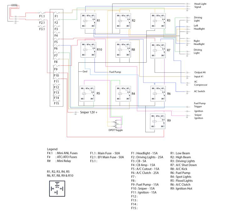 I also havent updated the fuse labeling in the above diagram either. This is my current layout for fuses. ATO/ATC Fuses F1 : Head light - 15A F2 : Driving Lights - 25A F3 : Spot Lights - 25A F4 : Flood Lights - 25A F5 : A/C Clutch - 25A F6 : A/C Cut Out - 15A F7 : Ignition Hot - 15A F8 : Fuel Pump - 30A F9 : Sniper Battery Hot - 30A F10 : CB - 5A F11 : CB Amp - 15A F12 : Dakota Digital - 15A F13 : F14 : F15 : Mini ANL Fuses F1.1 : F2.1 : F3.1 : I had originally setup just 15A for the Sniper battery hot but the battery hot for the Sniper harness also supplies power for the Fuel pump and they have it fused for 30A so I figured the red wire will still be the same 10ga power wire for the sniper so I will just fuse it at 30A as well. I hate to run a smaller gauge wire to the Holley connector even though the main hot and ground wire going into the sniper itself is still 10ga. The Mini ANL fuses I haven't decided on what rating I would use. If I add up all the fuses for the light circuit, it comes back to 90A and I don't think I want to have a 90A main fuse for the lighting circuit since that would require, I run something like a 10ga power wire and I had planned on just running two 12ga power wires for the two circuits.
"Old Blue" - '56 Fairlane Town Sedan - 292-4V, Ford-O-Matic transmission, 3.22:1
'63 Belair 2dr sdn - 283-4V, Powerglide transmission, 4.56:1 '78 Cougar XR7 - 351-2V, FMX transmission, 2.75:1 9inch "Bruno" - '82 F150 Flareside - 302-2V, C6 transmission, 2.75:1 9inch, 31x10.50-15 BFG KO2 |
|
|
Little update, I've been looking at connectors for the last hour or so trying to figure out what connectors to get. I will be using the Aptiv weather lock connectors, Aptiv is formerly known as Delphi which was OE standard on GM vehicles which tells me they are quality connectors.
I started off with counting the number of wires for each circuit. Front circuit 1, the circuit running to the front which will be the front lighting circuit I counted thirteen circuits in total all 16ga. I have three circuits for the headlight trigger that will plug into the OE headlight connector, I have six circuits for the left and right headlights, and I have four circuits for the two driving lights. That includes individual grounds for each light. I could reduce the number of grounds by tying the two driving light grounds into one ground and go from a 16ga ground each to a single 14ga ground. Seems like a waste to do that seeing as the grounds will all eventually tie into a single main ground within the fuse box itself. Front circuit 2, the circuit running to the battery will be three circuits, two power in 12ga and one ground in 12ga. The two powers will branch off inside to two separates Mini ANL fuses which will then split off to power a select number of fuses to help isolate the circuits in an attempt to prevent a short to ground blowing the main fuse and knocking everything out from EFI to lighting. Sniper Circuit, this circuit would be seven circuits, this would be the key hot for the sniper, the fuel pump trigger, the AC cut out for the sniper, the AC kick for the sniper, the two AC Clutch circuits, and the key hot trigger. Rear Light circuit I figured up 15 circuits, that would be the eight circuits for the four roll bar lights, the two circuits for the fuel pump, the CB circuit, the CB Amp circuit, the Dakota Digital circuit, and the main battery hot and ground circuits for the sniper. Now connector wise I found the following. Aptiv 8-pin 280 series which is good for 30 amps continuous. It comes with 16 and 18 ga terminals but I can buy 10, 12 and 14 ga terminals as well. I would like to use this for the rear circuits but even if I do one terminal for the fuel pump and rear light circuits that comes out to ten circuits. I could splice the individual ground wires of the lights into two bundles which would drop my ten circuits to eight circuits, and I can make do but I would have to do the math and figure up would simply going from 16ga to 14ga be enough for the grounds for the length of run or should I upgrade to a pair of 12ga circuits. I could use this for the sniper main power and ground but that's just two wires and I don't see the point in having an 8-pin connector for two wires unless I bundle the three circuits going inside for the CB, CB Amp, and Dakota Digital cluster with this, but those wires don't need to be that large, they could be 18 - 20ga and work just fine. Would be a waste of a 280 series terminal. Aptiv 16-pin 280 series which is good for 30 amps continuous. It comes with 12-16ga pins, and I could use this for the rear light connector. Only problem is the connector would be tee into the main power/ground wire coming from the sniper and I don't know how I could make that look proper. The interior circuit wires I can simply run them through this connector then break them out of the loom to go inside the cab under the heater box. I don't know how it would look to break the main power and ground for the sniper out a short couple inches past the connector. Might be better to just use a two pin 280 series connector for the main power and ground that would free up two circuits for the rear light connector dropping me down to thirteen circuits which would allow me to add the single trigger wire for triggering the ground of the spot and flood light relay under the dash. I can use this same connector for the front lights as the front light circuit is all 16ga. In the end on the fuses, I would have three circuits open, four if I give my sniper a Mini ANL fuse for power seeing as my fuse terminals provided with the box won't be capable of fitting a 10ga wire. My 16ga wire was a pain to get to crimp properly. I'm going to be depinning those terminals and applying solder just as a precaution for those terminals. The relay terminals themselves crimped nicely when I cranked down on them and the tug test on the wire showed no movement in the wire before I crimped the insulator stabilizer that bites into the insulation to take the load off the copper wire themselves. I will continue to search on amazon to see what my options are. I am trying to find the ATC/ATO terminals that will work in this fuse box I can't seem to find any. These have a bump on the side in line with the cut for the ATC/ATO fuse to fit between. This is what locks it into the box, all I keep finding are ones that has the tang on the side of the terminal and not the bottom when you lay the terminal with the crimp ears facing up.
"Old Blue" - '56 Fairlane Town Sedan - 292-4V, Ford-O-Matic transmission, 3.22:1
'63 Belair 2dr sdn - 283-4V, Powerglide transmission, 4.56:1 '78 Cougar XR7 - 351-2V, FMX transmission, 2.75:1 9inch "Bruno" - '82 F150 Flareside - 302-2V, C6 transmission, 2.75:1 9inch, 31x10.50-15 BFG KO2 |
|
|
Finalized update on the connectors.
Below are the following connectors that I purchased. Aptiv Metri-Pack 280-Series - 3-pin (10ga - 12ga terminals) Aptiv Metri-Pack 280-Series - 5-pin (10ga - 12ga terminals) Aptiv Metri-Pack 280-Series - 16-pin (16ga - 18ga terminals) Aptiv Metri-Pack 280-Series - 5-pin (18ga - 20ga terminals) Aptiv Metri-Pack 280-Series - 14-pin (16ga - 18ga terminals) This is the break down for the wiring. Aptiv Metri-Pack 280-Series - 3-pin : x2 12V battery (10ga) ; x1 Battery ground (10ga) Aptiv Metri-Pack 280-Series - 5-pin : x1 Sniper 12V battery (12ga) ; x1 Sniper battery ground (12ga) ; x1 A/C Clutch (18ga) Aptiv Metri-Pack 280-Series - 16-pin : x4 Auxiliary Light 12V battery (16ga) ; x4 Auxiliary Light Battery Ground (16ga) ; x1 Fuel Pump Power (12ga) ; x1 Fuel Pump Ground (12ga) ; x1 CB power (18ga) ; x1 CB Amp Power (18ga) ; x1 Auxiliary Light Relay Ground (16ga) ; x1 A/C Clutch trigger (18ga) ; x1 Dakota Digital 12V battery (18ga) Aptiv Metri-Pack 280-Series - 5-pin : x1 Key Hot Trigger (20ga) ; x1 Sniper Key Hot (20ga) ; x1 A/C Kick (20ga) ; x1 A/C Cutout (20ga) ; x1 Fuel Pump trigger (20ga) Aptiv Metri-Pack 280-Series - 14-pin : x1 High beam trigger (16ga) ; x1 Low beam trigger (16ga) ; x1 headlight relay ground (16ga) ; x2 Low beam (16ga) ; x2 High beam (16ga) x 2 headlight Ground (16ga) ; x2 Driving Light (16ga) ; x2 Driving Light Ground (16ga) I found out that I will have one terminal left over in the 14-pin connector for the front lights, I will be using that terminal in the 5-pin connector for the sniper to make my A/C clutch connection to run my 18ga wire from the box with the sniper wiring and break out by the distributor and going across the engine to the compressor clutch coil. The 5-pin connector for the Sniper was the only choice I could find on amazon as there were no 3 pin connectors with 10ga - 12ga terminals. This works for me as I will have to plugged terminals, I won't be using that I can use on the 16-pin connector for the rear light circuit for the 12ga wire for the fuel pump power and the 12ga wire for the fuel pump ground. Only thing I still have to buy is the plugs for these connectors so I can plug unused terminals. I also still need to get one more connector, at least a 8-pin 280-series connector for the roll bar auxiliary lights. I will be making my harness back to under the bed so I can shrink wrap the ends of the braided loom, the auxiliary roll bar light circuit will break out with a short four-inch pigtail and the end will be capped with the other half of the connector with plugs in all terminals. The two 12ga wires for the fuel pump will cross over on the cross member to the fuel tank under the bed where the wires will connect directly to the '85-'86 four pin fuel pump connector. From there my choices are two-fold, I can take and source a cheapie '82 sending unit and drill out the sending unit connector and fabricate an adapter that will plug into my OE sending unit double wire and convert it to the 4-wire '85-'86 sender connector which will allow me to revert at any time in the future if I strangely decide to. Or I could simply splice the sending unit ground wire into the fuel pump ground wire and make a simple single bullet terminal end on the sending unit wire to the OE connector. Drawback of doing it this way is it would be a 50/50 chance of plugging into the wrong terminal and having no fuel gauge, reusing the OE sending unit connector would ensure it can only plug in one way. I also need to get a 4-pin 280-series connector for my two driving lights, I will be redoing the deutsch connectors and instead of having the connectors above the bumper I will use shrink tubing and woven loom material to cover the power/ground wires and move them both behind the bumper and over to a 4-pin connector where they both will be connected out of sight. Same will be done with the roll bar lights, the 8-pin connector for them will be located under the truck, it will be one continuous wire through the roll bar to the lights themselves with no connector. This not only improves the look it also cuts out multiple connectors that can introduce a failure point. Plus, if I ever have to repair the wire, I can simply cut the wire solder the new wire to the old pull it through and make my connections under the truck again. I also purchased a Iwiss Metri-Pack crimper, I have a Deutsch crimper which also does the crimps for wires with the insulator tang and a standard crimper for doing insulated and non-insulated crimps. I to this date never had a need for the Metri-Pack crimper but now I do, I am just not a fan of the crimp on wire seals. The Deutsch terminals use a sliding weather seal that doesn't crimp to the terminal which I like. Hopefully the weather seals crimp nicely with the proper tool.
"Old Blue" - '56 Fairlane Town Sedan - 292-4V, Ford-O-Matic transmission, 3.22:1
'63 Belair 2dr sdn - 283-4V, Powerglide transmission, 4.56:1 '78 Cougar XR7 - 351-2V, FMX transmission, 2.75:1 9inch "Bruno" - '82 F150 Flareside - 302-2V, C6 transmission, 2.75:1 9inch, 31x10.50-15 BFG KO2 |
|
Administrator
|
Wow! If that was a "little update" I'm not sure I want to see a "huge update"!
 I've scanned it, though I've not truly studied it. I suspect you are doing as I do and getting things documented so you can keep track of what you have done rather than asking for input. But I do have some input. If the Iwiss crimper is the one I got you don't have to crimp the seals. It'll put the crimp through the narrow part of the seal nicely, but you can leave the seal to the rear during the crimp and it'll put the tangs through the wire's insulation just fine. I've done it both ways and I don't really know what I like best. But so far I've not had any problems with the crimped seals so perhaps that's the best way? 
Gary, AKA "Gary fellow": Profile
Dad's: '81 F150 Ranger XLT 4x4: Down for restomod: Full-roller "stroked 351M" w/Trick Flow heads & intake, EEC-V SEFI/E4OD/3.50 gears w/Kevlar clutches
|
|
|
lol Yep, it is a little bit of both. Getting my thoughts out there as well as some feedback in the off chance that there is a better way of doing it that I may not have thought of. On the crimper it is a iCrimp which is a sub brand of Iwiss. https://www.amazon.com/dp/B07476C1LD/ref=twister_B09N8LGMDS?_encoding=UTF8&psc=1 I thought about just leaving the second crimp undone and just slide the seal into place after the terminal was connected.
"Old Blue" - '56 Fairlane Town Sedan - 292-4V, Ford-O-Matic transmission, 3.22:1
'63 Belair 2dr sdn - 283-4V, Powerglide transmission, 4.56:1 '78 Cougar XR7 - 351-2V, FMX transmission, 2.75:1 9inch "Bruno" - '82 F150 Flareside - 302-2V, C6 transmission, 2.75:1 9inch, 31x10.50-15 BFG KO2 |
|
|
Looks like the screws are #10 machine screws. I tried both 10-32 and 10-24 and they both thread in with a little side to side play. might be the next size up, but at least knowing the right area I can look tonight and find a small assortment.
I did get my non insulated barrel crimp assortment and my marine waterproof shrink wrap in today, amazon seems to indicate a big chunk of my order will be delivered tomorrow.
"Old Blue" - '56 Fairlane Town Sedan - 292-4V, Ford-O-Matic transmission, 3.22:1
'63 Belair 2dr sdn - 283-4V, Powerglide transmission, 4.56:1 '78 Cougar XR7 - 351-2V, FMX transmission, 2.75:1 9inch "Bruno" - '82 F150 Flareside - 302-2V, C6 transmission, 2.75:1 9inch, 31x10.50-15 BFG KO2 |
|
|
I got quite a bit done on the fuse/relay box this weekend but couldnt finish as I need to source some extra supplies. I need to get three colors of SXL Crosslink wire in 18ga for my CB/CB Amp/Dakota Digital circuits. I also have to source some 10-24 x 1/4" machine screws for threading into the terminal blocks on the fuse/relay box. The ones I have from work are too long and I prefer not using nuts to hold the mini ANL fuse to the bolt that is on the inside holding the wiring tight.
These are the photos of the current state of my fuse/relay box. This first photo is showing the way too long machine screws that are holding the 10ga main power wire and the wires to the fuses. 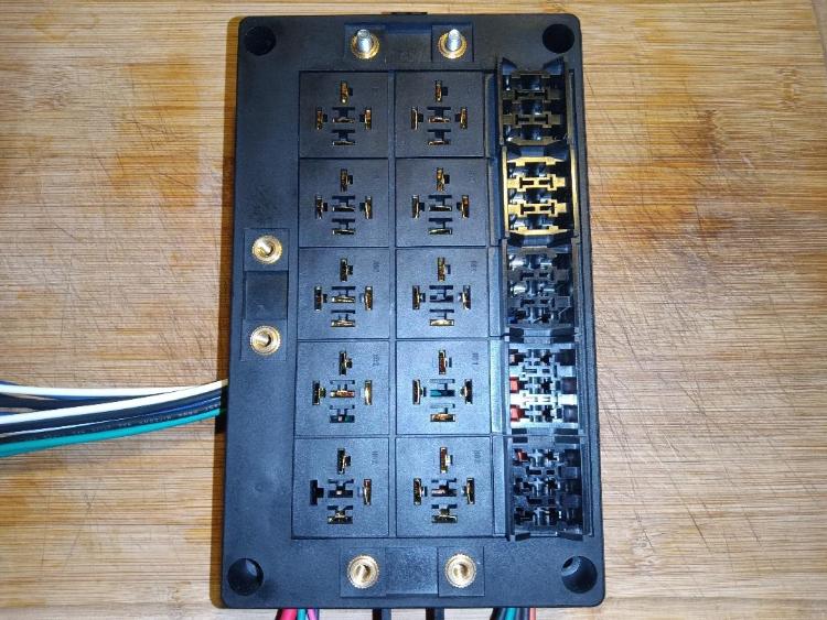 This second photo is showing the back of the box. The blue wire is what I am not sure about, I had to do the wire like that to jumper the trigger wire for the high beam relay to the driving light relay, the flood light relay, and the spot light relay. I could have gone with smaller gauge wire which would have allowed me to double up on the wires to the terminals but I was afraid of that not holding the wire as good as just one wire per terminal. The blue wire I can press down with some effort and settle it down where I should be able to get the plexiglass cover to sit on the back side. I also omitted the second 10ga power wire, it was getting too cluttered in the box and I honestly dont believe I need a second fuse to isolate the circuits. Each circuit has its own fuse already, the main fuse is just to protect pulling too many amps through the 10ga wire. I would have to do the math to calculate how many amps all my circuits are pulling but I know I will have to measure the total length of the main battery wire but I doubt it would be over 3 feet of total length and 10ga wire can handle 90A of current for 3ft of length. I doubt all my circuits combined would pull more than 90A but I would be using a 90A mini ANL fuse as this fuse is to protect the 10ga wire from being over loaded from my circuits. 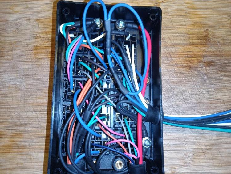 This photo is a close up of the two bundles of battery hot wires going to each fused circuit. I am using a 10ga eyelet and placing bundles of four wires in. The first eyelet providing battery power to the headlights, driving lights, spot lights, and flood light circuits are 16ga wires. The second eyelet is providing power to the A/C clutch, the AC cutout, Ignition Hot, and the fuel pump power wires. The A/C clutch wire is 18ga, the A/C cutout and Ignition Hot are 20ga, and the fuel pump wire is 12ga. I still have to make one more eyelet this time for three 18ga wires for my CB, CB Amp, and my Dakota Digital power circuit. 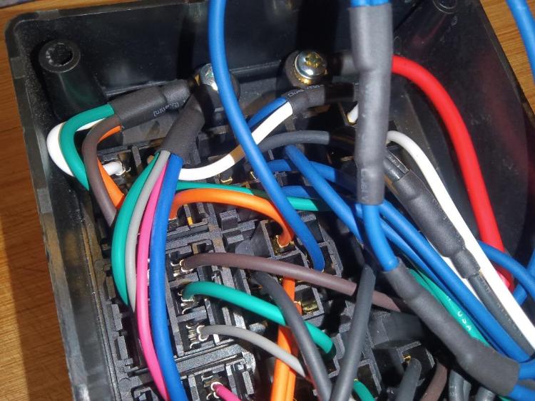 This photo is a close up of the ground terminal block. I have the four ground wires from the headlights and driving lights bundled into one eyelet and the relay grounds bundled into another eyelet. I still need to make two more eyelets, one eyelet will be four ground wires going to the rear for my two spot lights and two flood lights and the other eyelet will be a single 10ga main ground that will run with the 10ga battery hot wire which will connect straight to the battery. 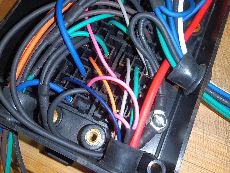 This photo is of the 14-pin Delphi Metri-Pack connector I made up for the front light circuits. I havent put the wire retainer strip in place yet as I need to get a set of terminal plugs so I can plug unused pins. This connector is for both headlights, headlight trigger circuit, and driving lights. 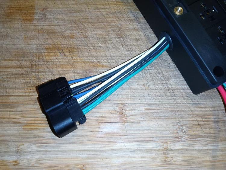 This photo is showing the largest 150A mini ANL fuse I got in a cheap assortment set sitting in place. I will most likely be using a 90A fuse. I would have liked to have split the circuits between two ANL fuses since I have three ports, as can be seen with the heavy gauge circuits I am dealing with I dont have the room for the wires. If I had a bussed circuit for the ATO/ACO fuses I could have freed up some space. 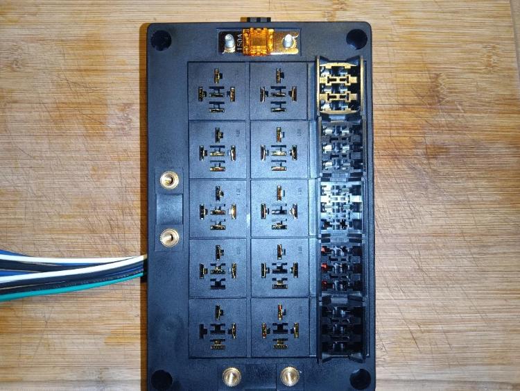
"Old Blue" - '56 Fairlane Town Sedan - 292-4V, Ford-O-Matic transmission, 3.22:1
'63 Belair 2dr sdn - 283-4V, Powerglide transmission, 4.56:1 '78 Cougar XR7 - 351-2V, FMX transmission, 2.75:1 9inch "Bruno" - '82 F150 Flareside - 302-2V, C6 transmission, 2.75:1 9inch, 31x10.50-15 BFG KO2 |
|
Administrator
|
I think it is looking great! And I don't see a need for another fuse. That 90A should be fine.
On the screws, don't you have something that cuts screws? Like one of the cheap crimpers? Mine works great to let me trim screws right to length. However, then you have an untreated end, and unless the screw is brass you could have a problem. Maybe that's what you are thinking of?
Gary, AKA "Gary fellow": Profile
Dad's: '81 F150 Ranger XLT 4x4: Down for restomod: Full-roller "stroked 351M" w/Trick Flow heads & intake, EEC-V SEFI/E4OD/3.50 gears w/Kevlar clutches
|
|
|
This post was updated on .
I think 90A would be fine as well. Just figuring up my circuits I have the following. Highbeams 55w (110w) : 3.79A (7.58A) @ 14.5v Driving Lights 100w (200w) : 6.89A (13.79A) @ 14.5v Roll Bar Lights 100w (400w) : 6.89A (27.58A) @ 14.5v CB Radio 2.5w : 0.17A @ 14.5v CB Amp 100w : 6.89A @ 14.5v Total : 56.01A @ 14.5v That leaves me 33.99A @ 14.5v to run the sniper, fuel pump, and dakota digital cluster. That also is heavily dependent on running 100w lights for the roll bar lights. I could very well toss the 100w bulbs for 55w bulbs to drop the amperage requirement, but I should be safe. I read that a 255lph high pressure/volume fuel pump at 43.5 psi (sniper runs at 50 psi) draws 8 amps. Could round it up to 10A. I don't know how many amps the sniper would draw; I doubt it would be more than 10A. The Dakota Digital cluster, the RTX cluster instructions state the battery wire should be 5 - 20A fused. So, I figure the cluster should draw between 3A to 15A. So, 56.01A @ 14.5v plus an additional 10A and 15A for the sniper and Dakota Digital brings me to 81.01A @ 14.5v leaving me just 8.99A to run my A/C compressor. I very well may have to run a second wire or at the very least isolate the Dakota Digital cluster to an ANL fuse with its own 18ga power wire. At least that would free up some 15A of power for the main wire. But for now, I can cut out some 27.58A of power as I don't have roll bar lights just yet. I also may go with the KC Daylighters in LED if I can get firm confirmation that the LED version will provide the same level of light pattern or just simply downgrade to just 55w bulbs or even instead of running four lights I could just go with two lights and make a decision on flood or spotlight. Or I could buy some 8ga wire and run it, but it won't fit my 3-wire connector as its only 10-12 ga. I could take and relocate the eyelet for the feed wire to another ANL fuse if need be. I may have to lengthen the wires however as it may not reach. On the screws, I thought about cutting them but the biggest issue with cutting screws is it damages the starter threads. Normally I thread a die on before I make my cut then bevel the cut end on a belt sander and then unthread the die clean the threads up. With a bolt only 1/4" in length there isn't enough thread to do this. I did find some allen button headed screws on amazon in the right size, but I rather have phillips so I don't have to carry a huge assortment of tools to do work on the side of the road. I am thinking about hitting the local hardware store up this weekend it is where I got some polished stainless steel hex head bolts for the license plate on my '56. If the bolt exists, they have it at this hardware store. They are just a bit pricy which I am not real crazy about.
"Old Blue" - '56 Fairlane Town Sedan - 292-4V, Ford-O-Matic transmission, 3.22:1
'63 Belair 2dr sdn - 283-4V, Powerglide transmission, 4.56:1 '78 Cougar XR7 - 351-2V, FMX transmission, 2.75:1 9inch "Bruno" - '82 F150 Flareside - 302-2V, C6 transmission, 2.75:1 9inch, 31x10.50-15 BFG KO2 |
|
|
This post was updated on .
Headers are boxed up in their original box with the Jet-Hot invoice tossed in. Going to UPS tomorrow to drop it off, hopefully I can get them to slip my Hedman Headers box inside another box just to double box it but keep it with in the dimensions of my current box.
Not sure how long the turn around will take but hopefully I will have my headers back ceramic coated in their Offroad 2000 in Titanium by the end of the month. Hopefully the coating isn't so thick that my headers that I clearance doesn't fit anymore. Exhaust wise, I still can't get word from Magnaflow on their inventory issue seeing as their aftermarket mufflers have been reduced to a fraction of what they normally stock. How ever I did find a guy online selling exactly the one I am looking for new in box for $95 compared to the new price of $110 before shipping. So, I am waiting to hear back from him to place the order for that muffler and then I will recoup as much as I can on the 2 1/4" version. Only thing left to do in the exhaust department then would be to pick up the Flowmaster stainless steel Y pipe and pick up an OE replacement muffler for our trucks to drill out the spot welds for the OE muffler hanger. This way I can mockup my exhaust system and mark where the hanger needs to be attached and then find a local exhaust shop that can weld steel to stainless steel to attach the OE hanger to my magnaflow muffler. Then just have to have the same shop custom bend me a 2 1/2" tail pipe routed like OE and I will give them the OE hanger off the replacement tail pipe I bought and have them weld that to the new tail pipe so I can retain as much of the OE hanger system as possible. For the electrical, I ordered from MonsterBolts some button head stainless steel machine screws 10-24x1/4" and they are too coarse. I ordered another set this time 10-32x5/16" in phillips head which should be right. I think the bin at work was wrong and the screws werent in the right place. Besides all that I am pretty close now. All I have left to purchase is as follows before I can start my install. This close to install I am starting to get jittery worrying about possible issues, I am back thinking about the cam bolt, then I was reviewing photos and will have to check my intake manifold gasket as it looked like in the photos the rear coolant passage might not be properly sealed which if it isnt, now is the time to R&R the intake manifold before I get it installed in the truck and waste coolant. 1) Cold Case 2-Core aluminum radiator : $481.20 2) '85 Fuel Tank : $91.79 3) '85 Sending Unit : $58.79 4) Walbro 255lph Fuel Pump GCA719-2 : $122.39 5) Fuel Pump Connector : $3.41 6) Fuel Tank Vent Valve : $14.82 7) Fuel Tank Vent Valve Seal : $5.66 8) InlineTube 3/8" Stainless Steel lwb fuel line : $55.00 9) Fan Shroud : $46.30 10) InlineTube C6 Standard Cooling Trans Cooler Lines Stainless Steel : $80.00 11) 3G Alternator ; Keep looking at the WAI Global 77563N2G that comes with a 2-groove pulley but I would have to disassemble to reclock it. I can get one with the right clocking but I would still have to pull the pulley off to swap on a single groove pulley. 12) Flowmaster Stainless Steel Y-pipe 2020057 : $454.95 ~Update~ I snagged the muffler, its a Magnaflow 13646 XL 3-Chamber stainless muffler. This is for the most part same dimensions as the one I currently have, 6" round body, 27" case length, 33" over all length. Only difference is the one I currently have is 2 1/4" and the one I snagged off ebay just now is 2 1/2". This is the route I decided to go, exhaust will be 2 1/2" from the Y pipe to the muffler and the tail pipe I will just find a local shop to make me a tail pipe in 2 1/2" shaped like the OE pipe. Maybe I could have them use the 2 1/4" tail pipe I got as a pattern to bend the 2 1/2" but I do know I want them to use the OE hangers that I will provide the parts that needs to weld to the pipes and I will also provide the band clamps for the exhaust so its not welded up so I can easily disassemble in the future.
"Old Blue" - '56 Fairlane Town Sedan - 292-4V, Ford-O-Matic transmission, 3.22:1
'63 Belair 2dr sdn - 283-4V, Powerglide transmission, 4.56:1 '78 Cougar XR7 - 351-2V, FMX transmission, 2.75:1 9inch "Bruno" - '82 F150 Flareside - 302-2V, C6 transmission, 2.75:1 9inch, 31x10.50-15 BFG KO2 |
|
|
Headers were supposed to ship out April 11, I lucked out a couple weeks ago they sent me the bill, after shipping and insurance both ways plus the Off-Road 2000 series coating I ended up paying right at $670. Ceramic coating itself was $585.
Should have got the headers this past friday they were out for delivery and I was home all day but the UPS guy never knocked he just tossed the "Sorry we missed you" tag on the door and marked it as being sent to the UPS pick up point the next business day. So I missed out on putting the headers on this past weekend as well as mocking up the oil dipstick tube. I ended up getting the headers today and I had just enough light to get the headers on today and grab some photos. I left the third bolt from the rear on the driver side out that is the bolt that the OE dipstick bolts to. My plan is to get some all thread or an ARP stud that I can screw in then use a ARP washer and nut hopefully in 3/8" head to tighten the header to the head then I can make a piece of stainless steel spacer to space the dipstick out like the manifold did and lock it in place. At the end of the day I am quite happy with going with the Off-Road 2000 coating in Titanium color. It looks very much like bare stainless steel/steel and the rough sand paper texture of the Off-Road 2000 coating kind of gives the illusion the headers are steel tubing but actually cast steel. I like it so much better than the black color I have been seeing with the black paint applied to the headers out of the box. Just too much black and blue now the Titanium color adds a little touch of accent color to break up all the blue and black. 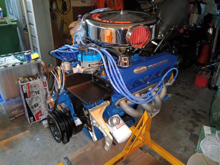 Close up showing the sand paper texture that gives a cast look that I actually like. 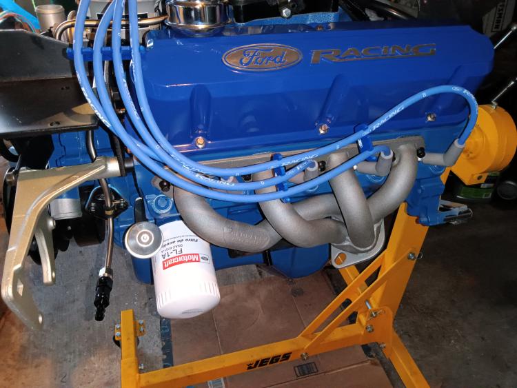 Passengerside with the stainless steel O2 plug installed. I put a decent amount of copper antiseize on it in the off chance I ever need to pull the plug. I will check with the tuner I will be using and see if he thinks that is a viable source for the O2 sensor which I dont think it is. 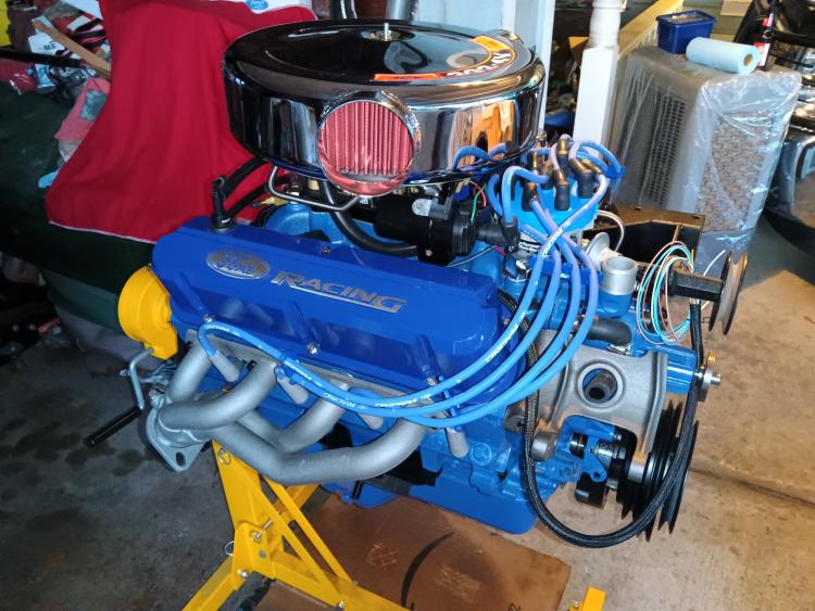 Close up of the passenger side with all header bolts installed. 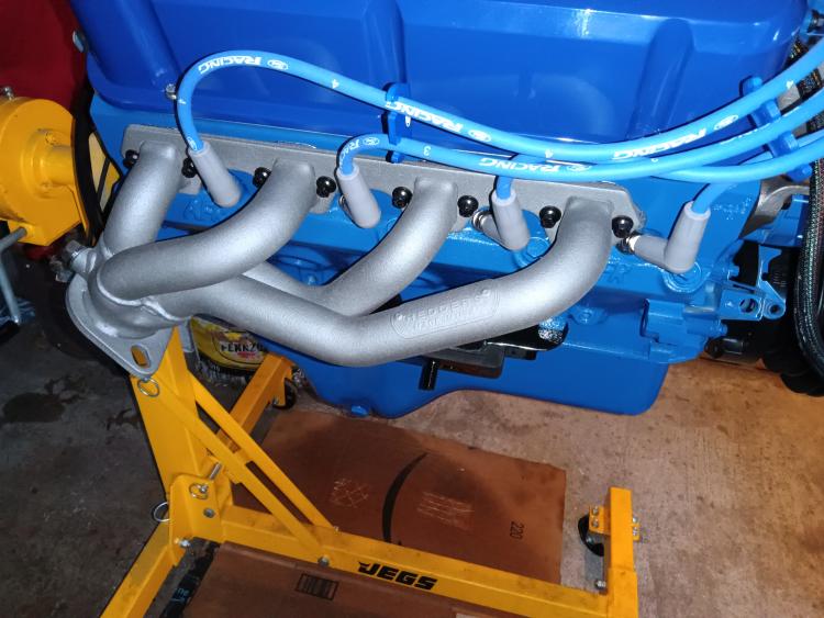
"Old Blue" - '56 Fairlane Town Sedan - 292-4V, Ford-O-Matic transmission, 3.22:1
'63 Belair 2dr sdn - 283-4V, Powerglide transmission, 4.56:1 '78 Cougar XR7 - 351-2V, FMX transmission, 2.75:1 9inch "Bruno" - '82 F150 Flareside - 302-2V, C6 transmission, 2.75:1 9inch, 31x10.50-15 BFG KO2 |
|
|
They look nice!
Dane
1986 F250HD SC XLT Lariat 4x4 460 C6-Sold 1992 Bronco XLT 4x4 351W E4OD 1998 GMC Sierra SLE K1500 350 4L60E Arizona |
|
Administrator
|
Looking really good!
 And I do like the color and texture. Good choice. Plus, I agree with you that the O2 bung is too close to a cylinder to use.
Gary, AKA "Gary fellow": Profile
Dad's: '81 F150 Ranger XLT 4x4: Down for restomod: Full-roller "stroked 351M" w/Trick Flow heads & intake, EEC-V SEFI/E4OD/3.50 gears w/Kevlar clutches
|
|
|
Thanks, I was really happy with how they came out. Looking at photos online I wasnt sure how the Titanium color would look as photos online made it look like a charcoal gray to a lighter raw steel gray. Mine ended up looking more like a lighter raw steel gray and the flash made them a bit lighter than they actually are. But they look so much nicer than the black they were painted in for shipping from hedman. Thanks, I was a little apprehensive about the color but just went with it cause it seemed to be a popular color outside of the standard silver and black both of which I didnt want. The texture I was shown looked way rougher than what it actually does on the headers but for cleaning you cant use a rag or a car wash mitt, the roughness will catch and pull pieces off. I will use my soft bristle body brush when it comes time to wash under the hood. I dont know if I want to take a risk with trying to use engine cleaner like at the car washes on the headers considering they would be hot on the drive and they stress to clean them while they are ice cold. Im thinking about putting the O2 bung in the Y pipe about 2" below the flange this should keep it far enough away from the cross over pipe between the two banks merging as you can in the following photo of the Y-pipe I will be using. Im really concerned about reversion possibly pulling exhaust through the cross over pipe and having an effect on the O2 reading. In reality I will be having it tuned and Im sure he will limit the changes the O2 sensor will be allowed to make to the tune to preserve the tune. I just want to make sure I dot all I`s in this case since I am reaching the end and the money is adding up. I got my alternator adjustment arm in, its a NOS unit that is for the 70/100 Amp alternators and is a different part number than the 40/60 Amp alternators. I havent compared side by side but I think I will use my junk 1G alternator I have mount it up and see if this bracket lines up properly still, I dont think there was a size difference between 1G alternators but there could have been. I know the 75A 1G on my '78 Mercury without placing them side by side looks identical to the 1G on my truck. Im really curious to find out this weekend if I need to flatten the NOS adjustment arm I got or if it can be used as is. Im also anxious to pull the dipstick out of my truck and start mocking it up this weekend to see how I want to go about it. My line of thought is a piece of all thread or a long ARP stud threaded into the header mount then use a ARP washer and nut to tighten the header in place then make a spacer to go between the nut and the dipstick to position it properly like it was with the exhaust manifold. Im not sure if I want to use a raw stainless steel spacer like I did with the stainless steel oil pressure sending unit extension or just see if ARP makes them or someone else that makes them in the black oxide finish to match the hardware on the headers. This is the photo of the Y-pipe from flowmaster I will be using sans converter. Its stainless steel and its listed for a '86 - '95 F150/bronco with a 5.0/302 engine. I checked the Y pipe part number and 85/86 came back with the same part number so it should work easily on my '82 as 80 - 86 trucks were the same. I am thinking no more than halfways between the flange and the cross over pipe is where I would put the O2 sensor, exact platement will be determined once in the truck mocking it up as I want the O2 sensor to be as vertical as possible but still removeable without dropping the exhaust. 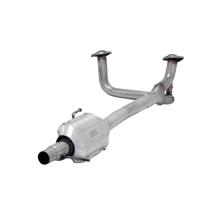
"Old Blue" - '56 Fairlane Town Sedan - 292-4V, Ford-O-Matic transmission, 3.22:1
'63 Belair 2dr sdn - 283-4V, Powerglide transmission, 4.56:1 '78 Cougar XR7 - 351-2V, FMX transmission, 2.75:1 9inch "Bruno" - '82 F150 Flareside - 302-2V, C6 transmission, 2.75:1 9inch, 31x10.50-15 BFG KO2 |
|
Administrator
|
I think the O2 sensor in the crossover is good - if it doesn't hit anything.
Gary, AKA "Gary fellow": Profile
Dad's: '81 F150 Ranger XLT 4x4: Down for restomod: Full-roller "stroked 351M" w/Trick Flow heads & intake, EEC-V SEFI/E4OD/3.50 gears w/Kevlar clutches
|
|
|
You mean the existing O2 bung that is situated between the two Y pipes? I would have to show it to my tuner and get his opinion, if it would work there Id rather put it there than have to plug it. I just am unsure on this as I know the scavenging effect from bank to bank will cause exhaust to be pulled back and forth through the cross over pipe and I am not sure if it would be fine or not. I have installed O2 sensors after a merger of both sides before but I also let the sniper do the tuning on those builds. This one I will have this guy I know tune it as I want to get the most out of the aftermarket EFI.
"Old Blue" - '56 Fairlane Town Sedan - 292-4V, Ford-O-Matic transmission, 3.22:1
'63 Belair 2dr sdn - 283-4V, Powerglide transmission, 4.56:1 '78 Cougar XR7 - 351-2V, FMX transmission, 2.75:1 9inch "Bruno" - '82 F150 Flareside - 302-2V, C6 transmission, 2.75:1 9inch, 31x10.50-15 BFG KO2 |
|
|
Have to revisit the dipstick, I have an issue I have to resolve. What I had planned on doing isnt viable. The threaded rod and the 7/16" stainless steel tubing clears the headers but to position the dipstick in the right place I cant get a nut to tighten down as the nut contacts the header tube before.
So I have two options. First option is I am looking at a 86 or 87/ dipstick which from the photos I seen moves more forward and mounts off the second manifold bolt which I may be able to tweak the tube or bracket to fit the front most bolt. Second option is to get a mustang dipstick that I found at Late Model Restorations that claims it has already been clearanced for use on headers. Down side with this is the dipstick lays close to the engine which may make it harder to get to the dipstick than it was with the truck stick I currently have. I may be able to reuse my truck dipstick with the mustang tube if the sticks are both the same length this would give me a longer handle to make it easier to reach. Down side is it appears the mustang dipstick mounts on fourth bolt from the front. I may be able to bolt it all down then grab the tube and tweak it away from the engine some to make it lay away some. The 87 or 87/ dipstick would be hard to source as there are no reproductions and Jeffs Bronco Graveyard has the tube but not the stick itself, so I am leaning towards the second option and if I go this option I have to decide do I strip the zinc coating off and paint it engine blue/underhood black or leave it in the bare metal with zinc coating. Sucks because I had everything I need to do fabrication and had plans to paint the dipstick tube and install it. Now I have to wait another week as I have to decide which way to go which most likely will be the mustang dipstick route as I can buy it new vs trying to source a truck one.
"Old Blue" - '56 Fairlane Town Sedan - 292-4V, Ford-O-Matic transmission, 3.22:1
'63 Belair 2dr sdn - 283-4V, Powerglide transmission, 4.56:1 '78 Cougar XR7 - 351-2V, FMX transmission, 2.75:1 9inch "Bruno" - '82 F150 Flareside - 302-2V, C6 transmission, 2.75:1 9inch, 31x10.50-15 BFG KO2 |
| Edit this page |