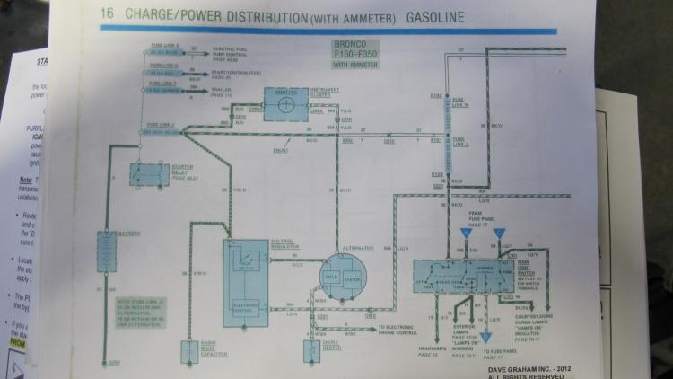
Gary, since I was taking a pic of the Painless diagram I thought I might as well take a pic of the EVTM, but yes an electronic version would no doubt have been more efficient...
I'm sticking with a 60 amp alternator. I have hardly any accessories(blower, radio, lights), so at this time I don't think I need anything more.
Don't suppose I need the MIDI fuse either, but is it a good idea too put it in there now? I'm leaning that way. And I would obviously like to go with all the new wires, but I'm willing to go with the old.
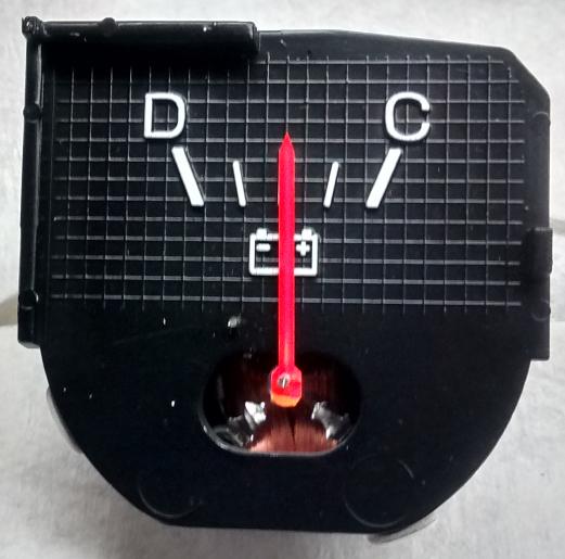
And yes, my main reason for going through this is the thought of having a gauge that doesn't work is just too much!

Rob
Eddy Myrtle '84 F150 300-6, Offenhauser C series intake, Edelbrock 1404(500cfm manual choke), EFI exhaust manifold, HEI dizzy, custom Painless harness, NP 435, NP 208, D44, 8.8"/3.08, 1.5" leveling coils, 265/75/16 tires.
Toyopet (Daily driver) '86 Toyota Pickup


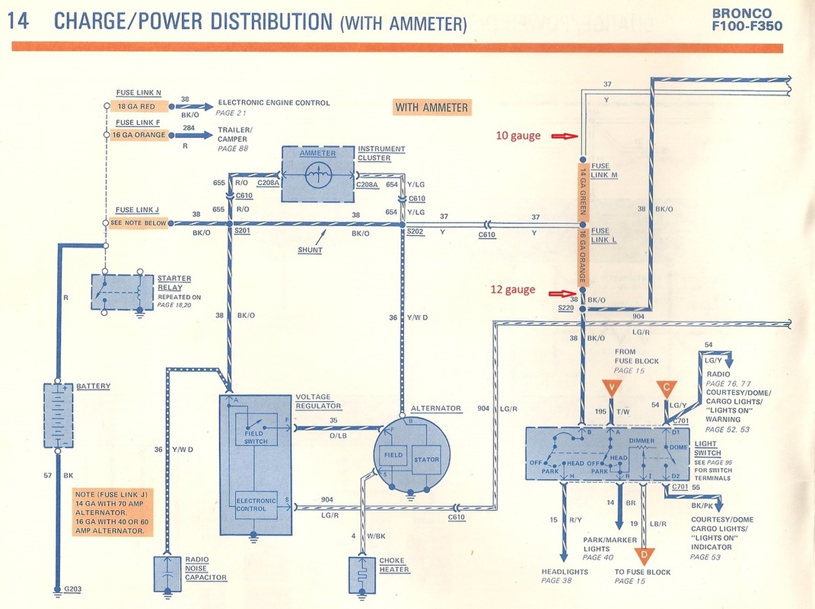

 ) So that would suggest you should connect the BK/O #38 that's connected to Fuse Link J in the diagram I posted to the new fuse.