Inertia Switch ('85 EFI dual tanks)

Inertia Switch ('85 EFI dual tanks)

|
This post was updated on .
Inertia Switch appears to have a problem.
The reason I'm checking it is because the fuel lines need to be depressurized. The plan is to install new gas tanks but the fuel lines have to be disconnected so don't want to squirt fuel from a pressurized line. (1) The white button on the top is totally "loose" and the directions I've read say that one needs to pry it up with a small screwdriver. Don't understand why it should be loose unless there is a problem with it. (2) Haven't hit anything nor made any sudden stops. (3) I've read that the catalytic converter can cause it to shut off but I don't even know if the exhaust has one, and at 44K miles it shouldn't be a problem unless there is an issue with the exhaust gases. (4) There is no clicking sound from the high pressure pump that I've been able to hear, and there is a problem with keeping the engine running. There has been some rust in the fuel when the high pressure pump filter was changed but that has been mostly gone. (5) As for fuel filters, the '85 pickups had a mixture of filter installations; some with one, some with two, and some with all three: (a) High pressure (HP) pump, (b) filter after (toward the engine), and, (c) one before the HP pump (toward the tanks). I haven't located either of the other filters, only the HP filter. It appears there is only the HP filter on this rig but I'll be checking one more time as maybe I was looking in the wrong place for the downstream (toward the front) filter. (reference: FUEL LINES and RELATED PARTS, top diagram) Anyone have an idea why the top button should be so loose? Does it have to be energized? Or can it be broken? Or is it normal? Checked the button with the power on (Key on but engine not running) and it was loose. 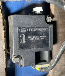 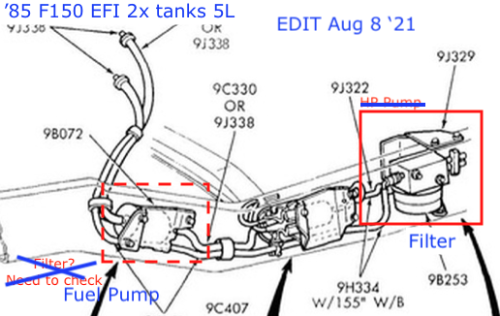 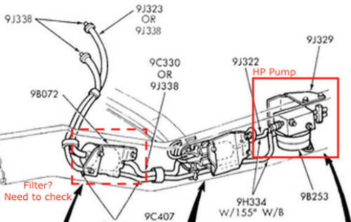
-= John =- 1985 F-150 EFI 302/5.0L dual tanks, long-wide bed, "heavy-half"
|
Re: Inertia Switch ('85 EFI dual tanks)
|
Administrator
|
Lets take it one issue at a time, starting with the inertia switch. Below is the diagram from the 1985 EVTM of your circuit, and you can see Connector C119, which the EVTM says is "near the inertia switch". I'd unplug it and check to see if the inertia switch itself has continuity.
Having said that, you do have a DVM, right? 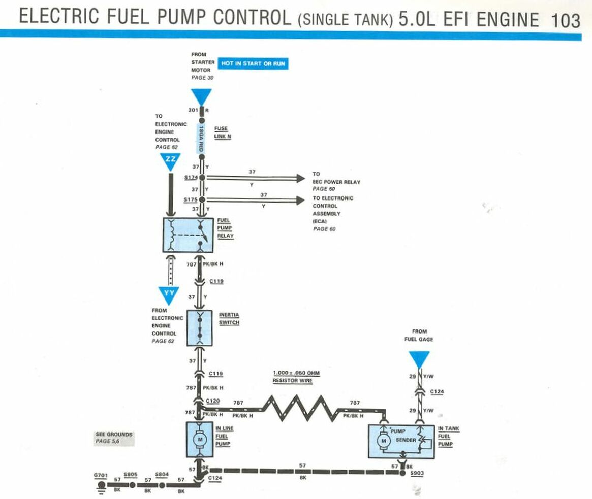
Gary, AKA "Gary fellow": Profile
Dad's: '81 F150 Ranger XLT 4x4: Down for restomod: Full-roller "stroked 351M" w/Trick Flow heads & intake, EEC-V SEFI/E4OD/3.50 gears w/Kevlar clutches
|
Re: Inertia Switch ('85 EFI dual tanks)
|
|
Removed the Inertia Switch and measured the resistance between the two prongs that the wire cable connects to and it read 0.02/0.03 Ω with a Fluke 77. [edit: after testing again and holding the probes a few seconds longer, the reading settles down to 0.00 Ω]
Measured with the white button pushed down and pulled up; the readings were the same. When the button is pushed down to where it touches the case, it springs back up 2 mm; all the way up with virtually no resistance (in force, not ohms) it is 6 mm off of the case. For info, it is a Dual Tank model but I would suspect the single tank at this point might be the same. I printed a circuit diagram which I think was for the dual tank, but didn't print the part that said "dual tank", nor the URL where I got it from. Spent some time trying to find the web page where it came from but couldn't find it again. The single tank appears to have the same circuit up to the Inertia Switch as the dual tank, and even has the same conductor code 37 Y and C119. However, after the Inertia Switch the circuit changes and isn't the same. (saved the file, see attachment). This is just in case it is needed going forward. 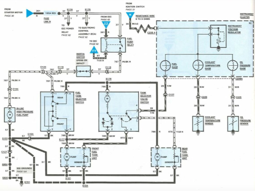
-= John =- 1985 F-150 EFI 302/5.0L dual tanks, long-wide bed, "heavy-half"
|
Re: Inertia Switch ('85 EFI dual tanks)
|
Administrator
|
If your DVM says there's no resistance then the inertia switch is closed and you need to look elsewhere for the problem.
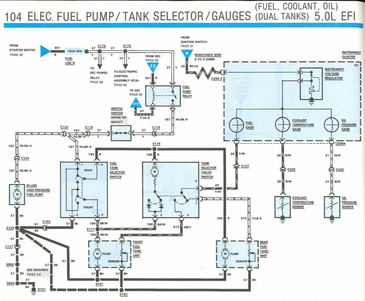
And to do that you need to follow along in that diagram. You "printed" Pg 104 of the 1985 EVTM, which you can find here: Documentation/Electrical/EVTM/1985 EVTM and then go down to the section on Electric Fuel Pump Control. As you can see, the inertia switch is after the fuel pump relay, so you can check at the inertia switch to see if the relay is coming in. You should have battery voltage on both sides of the switch with the ignition switch in Start or Run. 
Gary, AKA "Gary fellow": Profile
Dad's: '81 F150 Ranger XLT 4x4: Down for restomod: Full-roller "stroked 351M" w/Trick Flow heads & intake, EEC-V SEFI/E4OD/3.50 gears w/Kevlar clutches
|
Re: Inertia Switch ('85 EFI dual tanks)
|
|
Thank you, Gary. The url for the diagram location is very helpful.
1. Inertia Switch (IS) circuit voltage test: This was very difficult to do; spent a lot of time today trying to do it but access to the wire harness connection end points where it attaches to the IS is very difficult. The leads for the Fluke didn't seem to really reach the connector metal terminal ends because the voltage readings were between zero and about 0.2 or 0.3 which could be attributed to static electricity. Tried various things to contact the metal terminals but since they are recessed up inside the plastic case it was difficult. Elsewhere I've read to be careful about causing damage with the test leads. Due to the difficult access I tried everything from staples to making a couple small metal strips to simulate the two flat pins on the IS but even that was difficult. They don't make tin cans like they used to ... they're made of really thin aluminum now, and the tin snips had a difficult time cutting a narrow ~ 2mm strip with the thin meal. Then, it was difficult to put the strips into the end of the terminal. Could't get anything in the way of voltage. 2. Fuel Pump Relay (FP Relay), I guess, is the next step as I don't know where C119 is. The wire harness has an electrical tape covering. As part of prior troubleshooting the FP Relay was replaced even though I didn't know if it was bad. The wiring diagram shows four terminals and a switch. Would like to find a pin diagram with instruction about how to test it. Writing and numbers on the side: "Ford" E3TB 9345 A2A Probably jumping the gun at this point. Any suggestions from here?
-= John =- 1985 F-150 EFI 302/5.0L dual tanks, long-wide bed, "heavy-half"
|
Re: Inertia Switch ('85 EFI dual tanks)
|
Administrator
|
A number of Ford's connectors use 1/4" blade terminals, so if the inertia switch connector does you could just use some spare spade terminals.
But you really don't have to take the inertia switch out of the circuit. You just want to know if there is battery voltage on the output side, and you don't want to measure across the switch but from the switch to ground. So if the blade terminal approach won't work go get a straight pin and push it through the insulation near the inertia switch. Put your positive lead on that and your negative lead on ground and measure the voltage. As for a connector's location, you go to the EVTM section that shows the connector and scroll down to the last or next-to-last page where there'll be a list of connectors and locations. But I don't know anywhere that has a pin-out on the relay. But there are only 4 wires, so you can use the wire colors to determine what is what.
Gary, AKA "Gary fellow": Profile
Dad's: '81 F150 Ranger XLT 4x4: Down for restomod: Full-roller "stroked 351M" w/Trick Flow heads & intake, EEC-V SEFI/E4OD/3.50 gears w/Kevlar clutches
|
Re: Inertia Switch ('85 EFI dual tanks)
|
|
Bingo! Great idea! The blades are much smaller than 1/4", just measured one and it's a tad over 1/16", look closer to 2mm, and, they are thinner. That's no problem because I've got a lots of connectors so I can file one or two down to size. Actually, I was wondering about measuring the voltage to ground, tried it and that's where the ~0.2 > 0.3 V came up, but the difficulty was with trying to maintain the probe connection in a contorted condition on the seat to under the dash, while at the same time holding the the probes and the connector with only two hands. Will give it another try tomorrow. I'll check it out. Another good idea! .... And, the saga continues... (I'd hate to be a mechanic trying to earn a living! The word starvation comes to mind.)
-= John =- 1985 F-150 EFI 302/5.0L dual tanks, long-wide bed, "heavy-half"
|
Re: Inertia Switch ('85 EFI dual tanks)
|
Administrator
|
Good luck! Many of us have been through this sort of troubleshooting so have worked out ways to do it. And several of us have been intimate with the fuel pump relay circuit, although yours is slightly different from the one on my 460. Anyway, hang in there you'll figure it out.
Gary, AKA "Gary fellow": Profile
Dad's: '81 F150 Ranger XLT 4x4: Down for restomod: Full-roller "stroked 351M" w/Trick Flow heads & intake, EEC-V SEFI/E4OD/3.50 gears w/Kevlar clutches
|
Re: Inertia Switch ('85 EFI dual tanks)
|
|
Update:
The connector file-width in progress to compare it with those in the Inertia Switch; have to file some more. 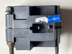 While filing down a connector to insert in the cable plug that connects to the Inertia Switch there was a discovery ... 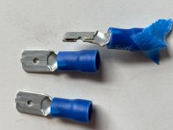 Spade connector with file job as compared to the original versions. Noticed that the spade is obviously made with thinner metal and that is folded over to make the spade thicker. The die that makes this has to be more complicated in order to blank and press at the same time, either that, or it is a multi-step process which is still more complicated. After testing with the spade connector in the wire harness connecter, there was still no voltage between it and ground. *sigh*. Off to the next step.
-= John =- 1985 F-150 EFI 302/5.0L dual tanks, long-wide bed, "heavy-half"
|
Re: Inertia Switch ('85 EFI dual tanks)
|
Administrator
|
The inertia switch was just an easy place to start, kind of in the middle. So if you don't have power to it then you need to move upstream. Check out the wires to the relay. The yellow wire should have power and when the relay closes the Pk/Bk is powered. But not if the relay doesn't close.
Gary, AKA "Gary fellow": Profile
Dad's: '81 F150 Ranger XLT 4x4: Down for restomod: Full-roller "stroked 351M" w/Trick Flow heads & intake, EEC-V SEFI/E4OD/3.50 gears w/Kevlar clutches
|
Re: Inertia Switch ('85 EFI dual tanks)
|
|
This post was updated on .
Good news: We have 12+V at the Fuel Pump (FP) Relay, Yellow 37 end.
 Also, There is a circuit diagram on the back side of the made-in-china relay: 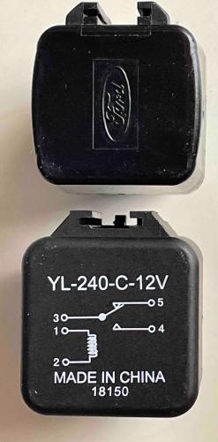 And for comparison, here is a picture of the pin layout of the china and OEM Ford Relays (complete with some dielectric grease): 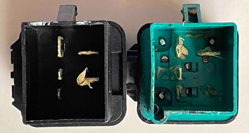 The horizontal top-right horizontal pin is opposite the Yellow wire. [Green relay = Ford] China relay has two horizontal pins The three vertical pins, #3, 1, and 2 correspond to the china relay diagram.
-= John =- 1985 F-150 EFI 302/5.0L dual tanks, long-wide bed, "heavy-half"
|
Re: Inertia Switch ('85 EFI dual tanks)
|
Administrator
|
That is good news. Now, do you have power to the Pk/Bk wire coming from the relay to the inertia switch? If not we need to know if the computer is telling the relay to pull in.
Gary, AKA "Gary fellow": Profile
Dad's: '81 F150 Ranger XLT 4x4: Down for restomod: Full-roller "stroked 351M" w/Trick Flow heads & intake, EEC-V SEFI/E4OD/3.50 gears w/Kevlar clutches
|
Re: Inertia Switch ('85 EFI dual tanks)
|
|
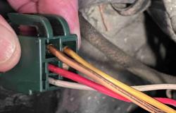
Can't figure out where to test to find out. At the Fuel Pump Relay, the Yellow is obvious, and its 12+ Volts. The Red is "probably" obvious because it is most likely "R" on the wiring diagram. There are two other wires listed in the wiring diagram that I can't make a "wire code" connection with: 1) T/LG D 97 that goes to the EEC 2) 787 PK/BK H that connects to the C118 (connector?) and then connects to the 37 Y running to the Inertia Switch. There are two colored wires of unknown color: One is a very light color in the picture, a very light shade of pink???, and the other that looks like a shade of brown. Tried to find the location of the C118 connector but was unable. The yellow "37 T" that goes to the Inertia Switch is wrapped in electrical tape and then disappears into a wire harness that is also wrapped in electrical tape, and then it disappears into the dark underside of the dash. Is there a table that says where the connectors, like C118, are located? (other than somewhere between the Fuel Pump Relay and the Inertia Switch?) Or, maybe what color wire of (1) and (2) would be the 787 PK/BK H? Thank you for all your help so far, this is progress.
-= John =- 1985 F-150 EFI 302/5.0L dual tanks, long-wide bed, "heavy-half"
|
Re: Inertia Switch ('85 EFI dual tanks)
|
Administrator
|
97 is tan with light green dots
787 is pink with black hash marks The pink wire goes to the inertia switch. You could test for continuity from the relay socket to the inertia switch plug... (the location of the connector (C118) is irrelevant if there is continuity) But my guess is that the EEC is not bringing wire 97 to ground and completing the pull-in coil circuit. My understanding is that the computer should initially ground this for a couple of seconds, then it waits for a PIP signal from the distributor pickup. The rising side of the PIP signal resets the countdown. If the engine is turning and the ignition is on, the EEC never times out and the relay stays closed. Additionally, the heavy EEC ground at the front of the battery negative terminal needs good connection. But if you've used a noid light to check injector grounding pulses already then that ground from the battery negative terminal should already prove good.
Jim,
Lil'Red is a '87 F250 HD, 4.10's, 1356 4x4, Zf-5, 3G, PMGR, Saginaw PS, desmogged with a Holley 80508 and Performer intake. Too much other stuff to mention. |
Re: Inertia Switch ('85 EFI dual tanks)
|
Administrator
|
Thanks for the help, Jim. Good suggestions.
Gary, AKA "Gary fellow": Profile
Dad's: '81 F150 Ranger XLT 4x4: Down for restomod: Full-roller "stroked 351M" w/Trick Flow heads & intake, EEC-V SEFI/E4OD/3.50 gears w/Kevlar clutches
|
Re: Inertia Switch ('85 EFI dual tanks)
|
Administrator
|
I will throw a suggestion out on these and some of the later systems. Ford used (as shown) some very strange relay configurations. Their function is the same as the pretty much standard Bosch 5 pin relays. Before I would put a Chinese relay of indeterminate quality in my vehicle, I think I would buy a relay kit (fog lights maybe) that uses a standard Bosch cube relay. Ford went to these in the later trucks with the PDC. These are some common (I shared some pictures a while back of Ford, Chrysler and GM relays, all had proprietary numbers but were interchangeable). I have several boxes of the various relays as they are so common and rarely do I find a bad used one from a junkyard. Of the Ford ones I had, two brown skirt and one green skirt, they were all bad. If you need one for underhood where the skirt is needed as a shield, Chrysler minivans in the 90s had a row of them on the left side underhood on a long bracket. These also feature a lock tab on the socket for some applications. Some will be 4 pin, which will work fine, the normally closed contact (Bosch 87a) is not on these, but the normally open (Bosch 87) is there and that is what turns on.
Bill AKA "LOBO" Profile
"Getting old is inevitable, growing up is optional" Darth Vader 1986 F350 460 converted to MAF/SEFI, E4OD 12X3 1/2 rear brakes, traction loc 3:55 gear, 160 amp 3G alternator Wife's 2011 Flex Limited Daily Driver 2009 Flex Limited with factory tow package Project car 1986 Chrysler LeBaron convertible 2.2L Turbo II, modified A413 |
Re: Inertia Switch ('85 EFI dual tanks)
|
Administrator
|
In reply to this post by Nemesis F150
C118 is only identified as a brown 2 wire connector located near the inertia switch. (I wanted to attach the page from the EVTM, but the forum will not open the "insert image" window for me today... )
Jim,
Lil'Red is a '87 F250 HD, 4.10's, 1356 4x4, Zf-5, 3G, PMGR, Saginaw PS, desmogged with a Holley 80508 and Performer intake. Too much other stuff to mention. |
Re: Inertia Switch ('85 EFI dual tanks)
|
|
In reply to this post by ArdWrknTrk
Jim - Great information!
Spent a lot of time this morning on the wire colors. To me, the Tan wire looked Pink and the Pink wire looked Tan; however, the markings, namely the Black and the Green did not match the wire color. Maybe I'm becoming color blind? Anyway, it appears the black markings are actually on the wire that looks Tan but must be Pink; and the Green markings are on the light-colored wire that looked Pink but must be Tan. The green markings are almost non-existent after 36 years. Took a picture of the connector and labeled the wires: 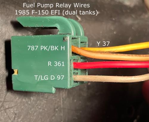
-= John =- 1985 F-150 EFI 302/5.0L dual tanks, long-wide bed, "heavy-half"
|
Re: Inertia Switch ('85 EFI dual tanks)
|
Administrator
|
Wires get crispy after 30+ years.
I spent yesterday afternoon chasing a bad wire in my parking lamp circuit. After changing out the switch and pigtail I ultimately ran a jumper from behind the fuse panel to the new socket. 😖 I hope you can figure out if 97 is seeing ground and pulling in the relay when you first turn the key to 'Run' Back probing that relay socket with a test light you can see from the driver's seat seems the easy way to accomplish that. If the ECM isn't responding and you have some soldering skills replacing the capacitors on the board is inexpensive and worthwhile since those caps go bad over time, even just sitting on a shelf!
Jim,
Lil'Red is a '87 F250 HD, 4.10's, 1356 4x4, Zf-5, 3G, PMGR, Saginaw PS, desmogged with a Holley 80508 and Performer intake. Too much other stuff to mention. |
Re: Inertia Switch ('85 EFI dual tanks)
|
|
In reply to this post by ArdWrknTrk
Continuity can be checked but I'll need a helper. Used to have a collection of short wires with alligator clips on the ends but don't know where they are. At the moment I'm not seeing any voltage at the Pink terminal end on this green connector. This may be related to what you wrote below. Only been testing with the ignition key at the Run (w/ engine not running) position, not the Start position. With the ignition key in Run position there is full battery voltage at the Yellow and Red wires, and a little over 1.0V at the T 97 wire. I don't have a noid checker and didn't know what it was until now. For what it's worth, the engine does run fine if it gets gas (don't use starter fluid, use only regular gas in a spray bottle) There are two ground wires on the battery, the large one that heads south, down below, maybe to the starter motor (?), and a small one that disappears into a wire harness that is wrapped in electrical tape. Unable at the moment to troubleshoot any further due to time constraints (thru today and tomorrow). Aft of the battery there is a group of ... relays(?), or something, behind a semi-protective plastic shield. I came across a circuit diagram that showed them but can't find it. They don't seem to have been an important part in this process (yet), though. Thank you very much for the explanation about how these things work so this was a good learning exercise. The old flat-head V-8s were much simpler. (FWIW, my first engine was a 4-cylinder Dort (car name) circa 1916, Model-T carb, on a set of Model-T rails. Hand-crank to start, manually adjust the spark advance, and no shop manuals or Internet. Things were simpler then.).
-= John =- 1985 F-150 EFI 302/5.0L dual tanks, long-wide bed, "heavy-half"
|
| Edit this page |