1G-to-3G and serpentine swap, R134a conversion, and gauge install on my 1985 F-150

classic Classic list List threaded Threaded
19 messages Options
Reply | Threaded
Open this post in threaded view
|

1G-to-3G and serpentine swap, R134a conversion, and gauge install on my 1985 F-150

Giraffe
This post was updated on .
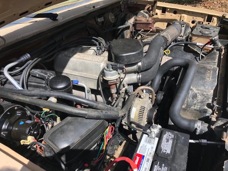
I undertook a semi-major project on the truck recently and completed it tonight. I installed 1994-1996 serpentine accessories, did a 130 amp 3G alternator swap, and installed all new A/C components to convert the truck to R134a (all the R12 was long gone). I figured I'd share my work.

Serpentine swap:

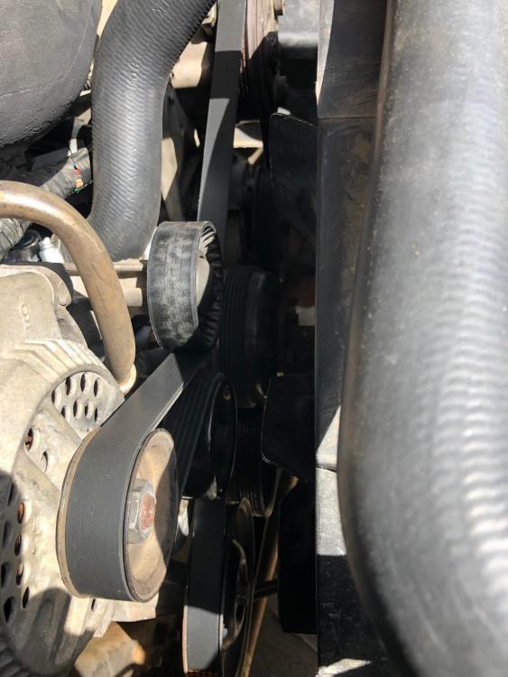
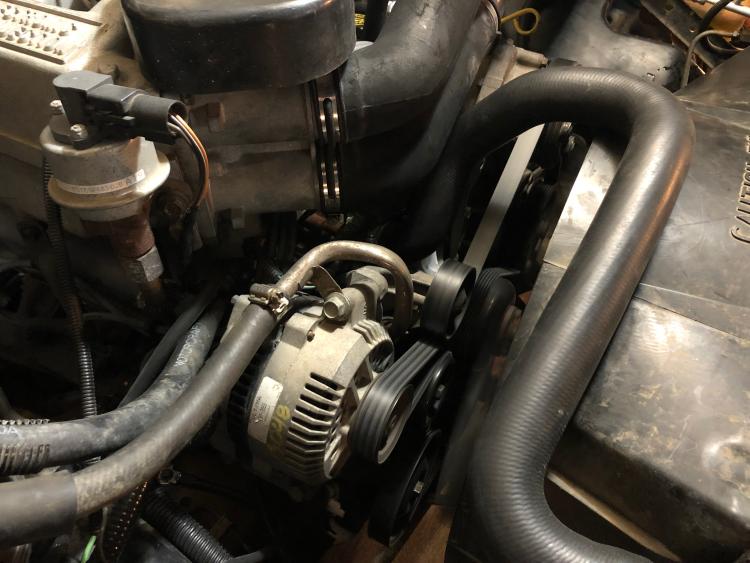
I pulled everything off a 1996 5.8 and a 1995 5.8 at the junkyard. I'm not 100% sure about the 1988-1993 front setup, but the 1994-1996 setup is interchangeable between the 5.0 and 5.8. Everything bolts to the heads. The only difference is the belt length between the two.

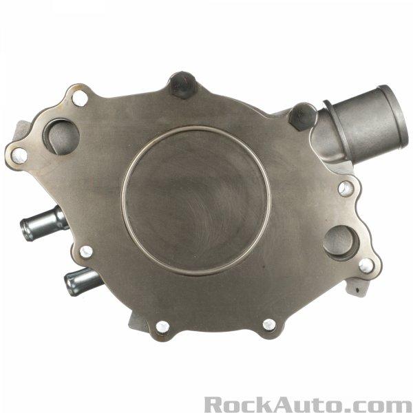
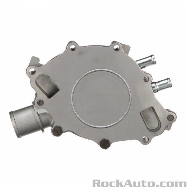
I eventually collected the following junkyard parts: power steering/air conditioning compressor bracket, alternator/smog pump/tensioner bracket, timing cover for reverse-flow water pump, 1994-1996 fan and clutch (this is required since the water pump will spin in the opposite direction).

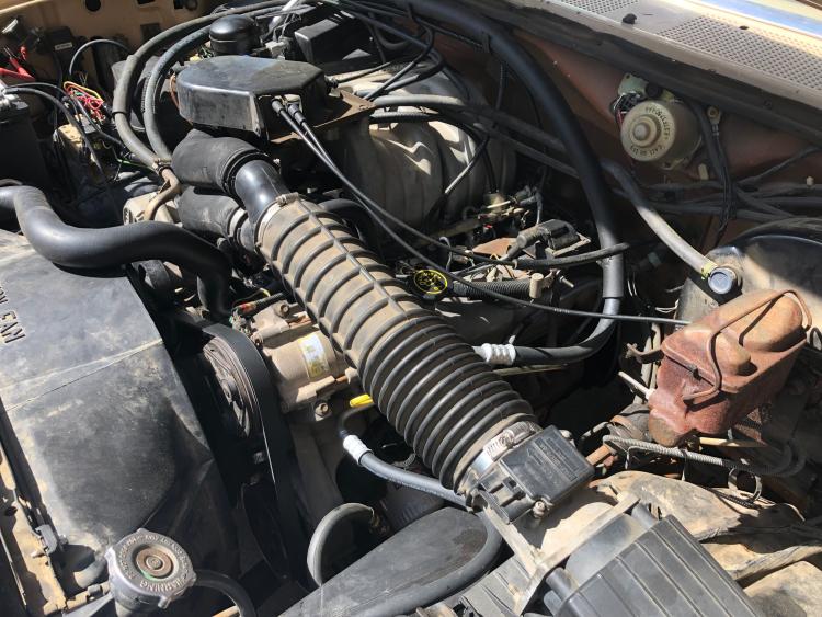
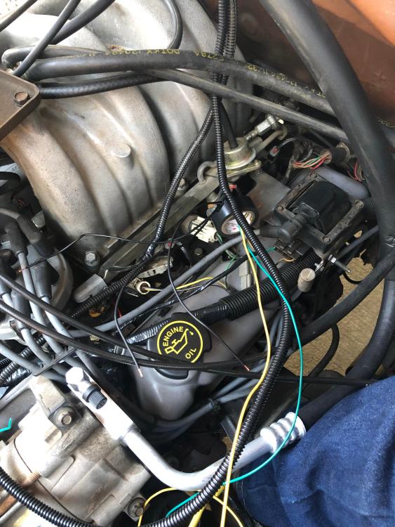
Oddly enough, I didn't take any pictures while I was in the process of doing the conversion. The serpentine setup is much more compact than the v-belt setup. I'm very happy with it. I also installed the later valve covers so I could have the oil cap I'm used to.


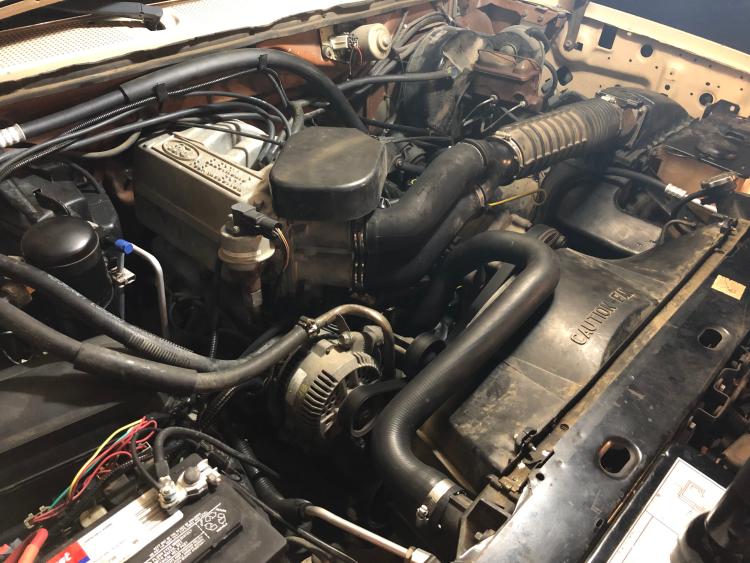
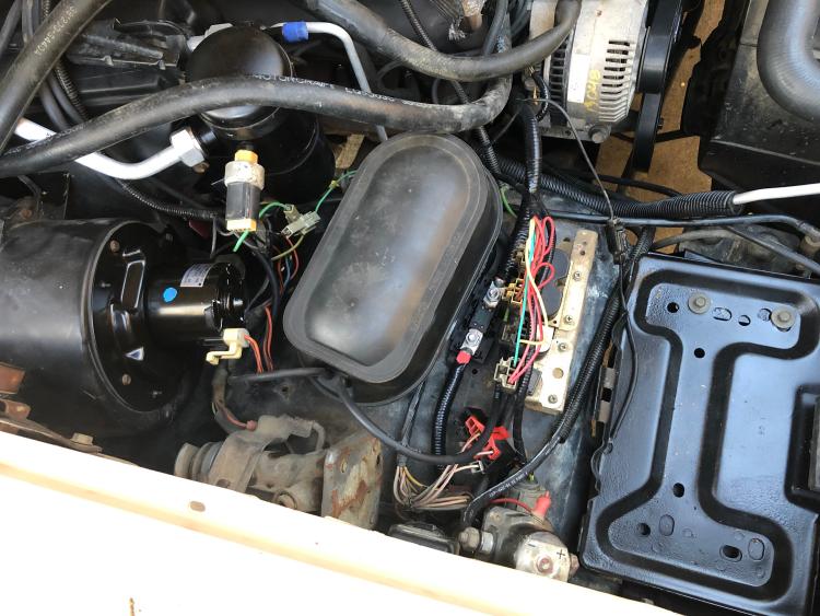
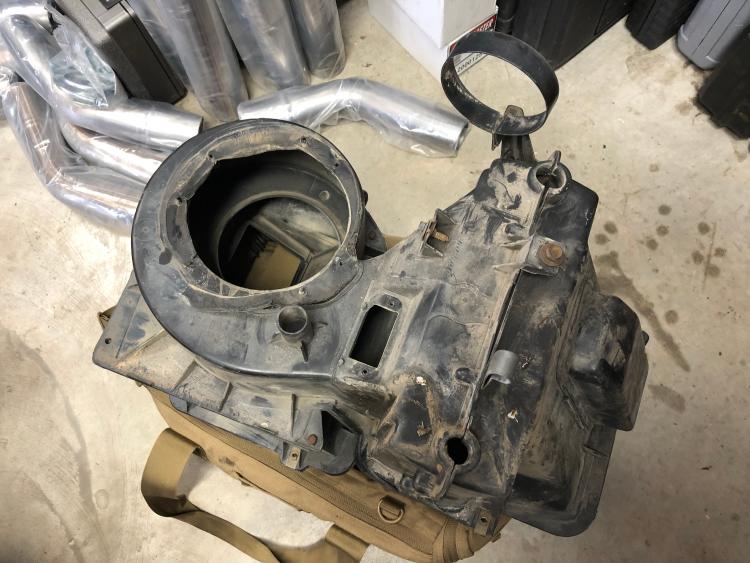
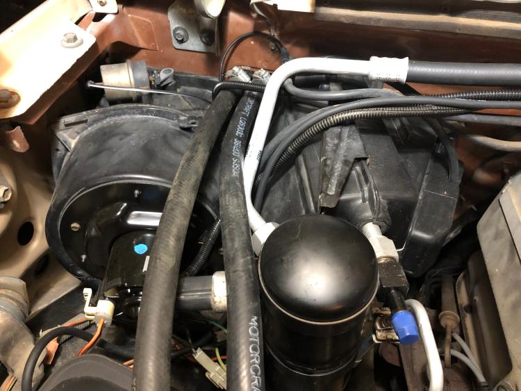
The R134a conversion was a much simpler affair. I used all new 1995-spec components. This required that I either modify my existing HVAC box or install a 1994-1996 HVAC box. I went with the latter since there was one available at the local Pick-n-Pull. There are three upsides to this swap: there is no longer a need to modify the box to fit the later evaporator and receiver-dryer, the newer HVAC box bolts up to the bullnose firewall like it belongs there, the HVAC box has a vacuum reservoir molded into it to operate the vent/recirculation vacuum motor. This allows you to eliminate the extra reservoir attached to the fender liner.

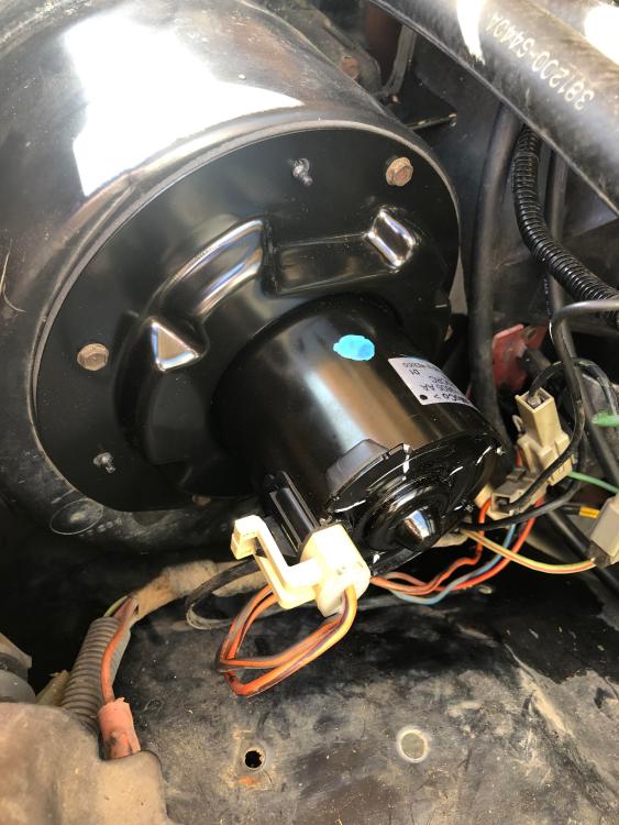
An extra bonus is that the 1985-spec blower motor plug fits perfectly in the 1995-spec blower motor. I was pleasantly surprised.


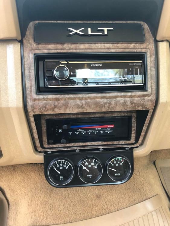
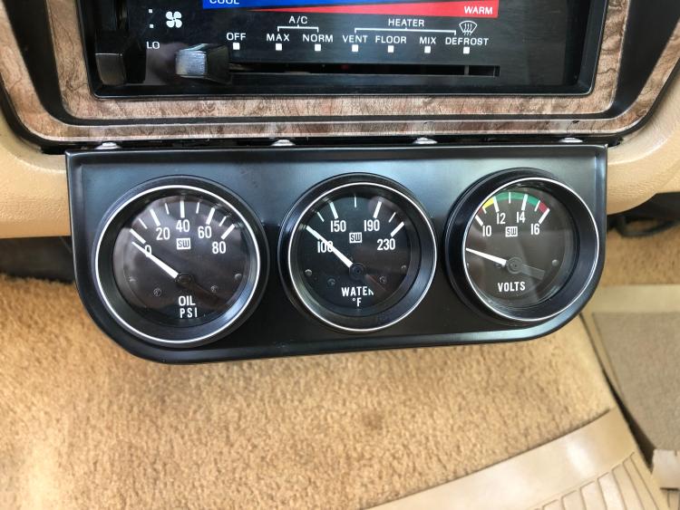
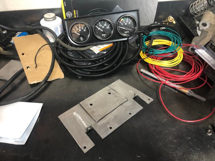
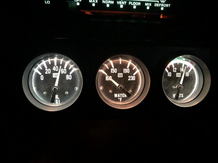
The gauges I installed are a set of three Stewart Warner gauges in a VDO three-gauge panel.

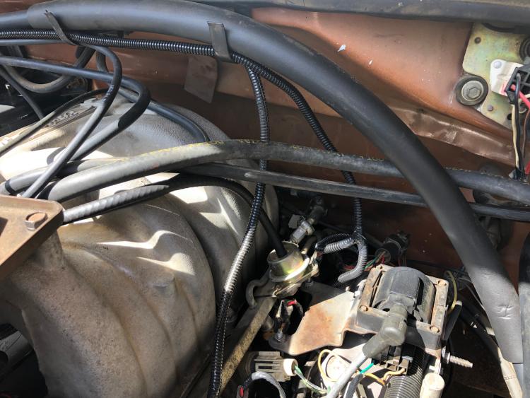
The instructions (yes, I read those) state to use an engine ground for the gauges. With this in mind, I decided to use the engine ground that Ford used for the engine-to-firewall. I ran all the wires from the cab to the engine bay through the grommet hole on the top of the HVAC box. This was logical since the later model HVAC box has a larger hole since the harness for the blower motor passes through there rather than simply the vacuum supply and reservoir lines on the 1985. This gave me an easy route for the wires with plenty of room.

I fabricated this bracket for the gauges out of 16-gauge steel I had left over from when I built my welding cart. It uses two screws that secure the bottom part of the dash to the dash structure along with two screws that use the bottom attachment for the HVAC controls.


I painted it black, added some foam tape to stave off any rattles, and the riveted the gauge panel to it.


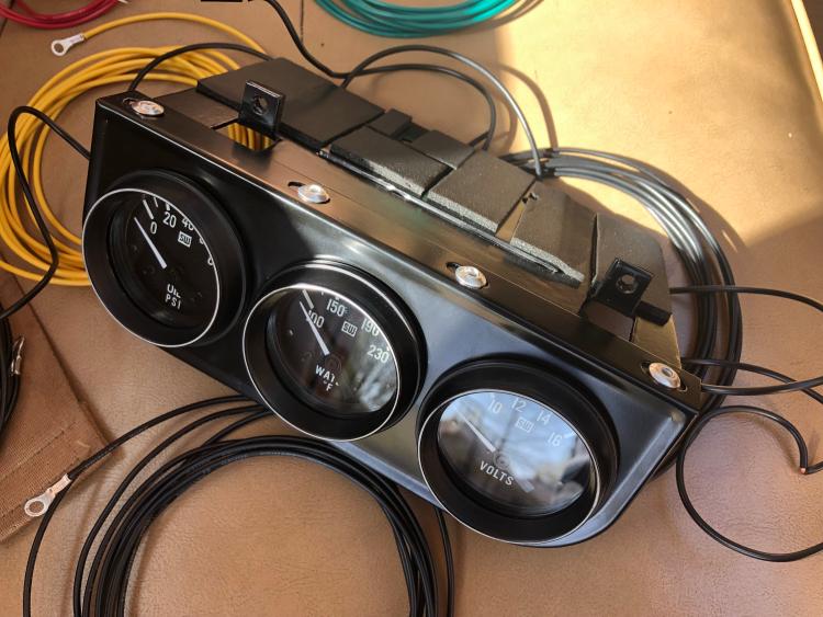
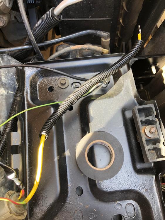
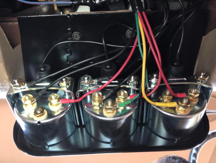
I wanted to make the wiring as clean as possible. I bought ten feet of ¼" loom (which ended up being just enough) and routed everything as best I could. I didn't want wires everywhere. I used black for all grounds, yellow for the oil pressure sender, green for the water temp sender, and red for all switched ignition.

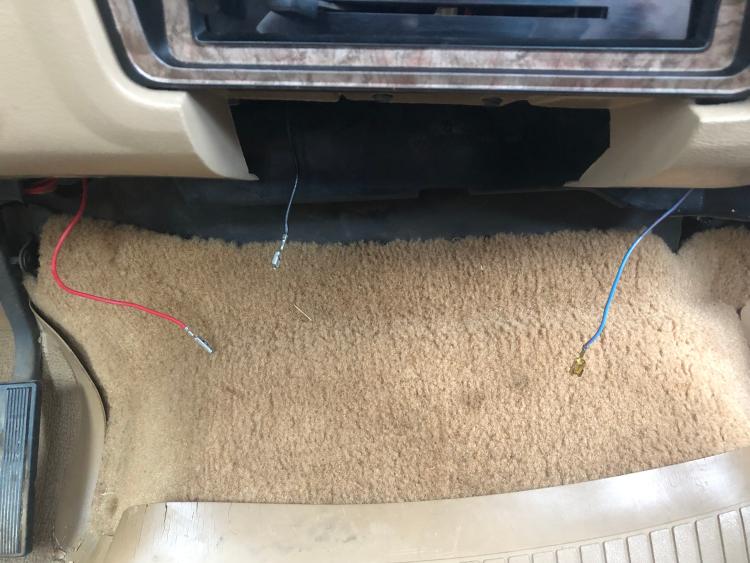
I removed the ash tray and cigarette lighter since I won't be needing it. This also gave me easy access to an illumination source for the gauges. In this picture, I've tucked away the power wire for the cigarette lighter since I didn't use it. The black wire is the ground for the lighter. I was planning to use this to provide ground for the gauge illumination, but decided to use a chassis ground on the dash structure instead. The blue/red stripe wire on the right is the plug for ash tray illumination. I de-pinned power wire from the connector and tucked away the connector with the ground still in it. I used this wire to provide illumination for the gauges. I'll get to the red wire on the left in a moment.


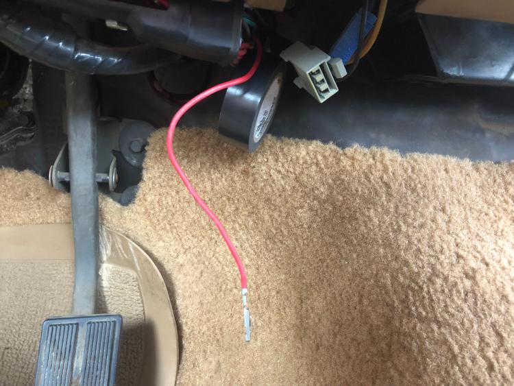
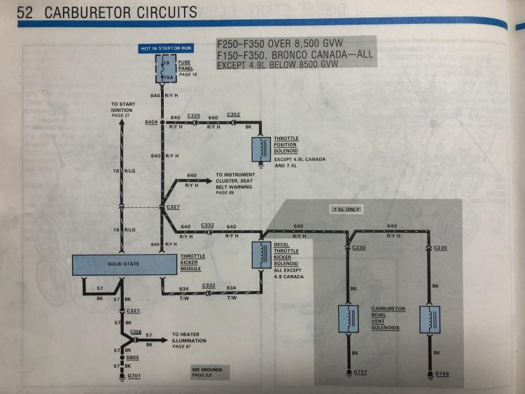
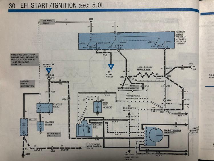
The wire on the left is something I was able to use since I have a 5.0 EFI truck. This wire is originally part of connector C327. On a carbureted truck, this provides power to the throttle kicker. On an EFI truck, this connector is there, but is not used. I de-pinned this wire from the connector and tucked the connector away. This connector receives switched 12V in start and run with a 15 amp fuse. It's perfect to provide switched power to the gauges.


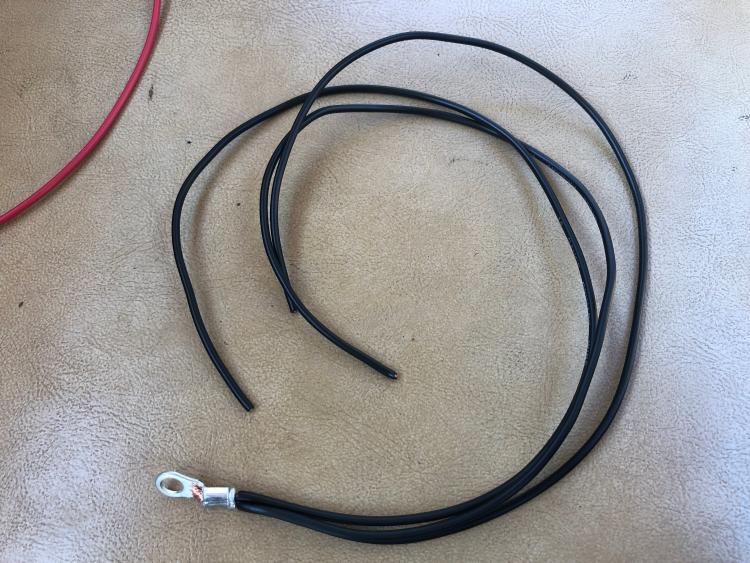
To provide illumination to the gauges, I used the aforementioned wire from the ash tray light and made a common ground cable for the gauges.


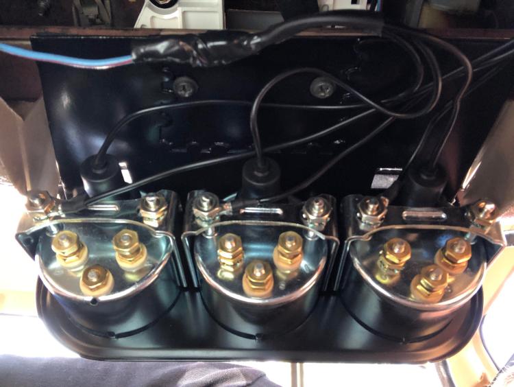
You can see the illumination wire up top with the three grounds for the gauge illumination attached to the mounting brackets.


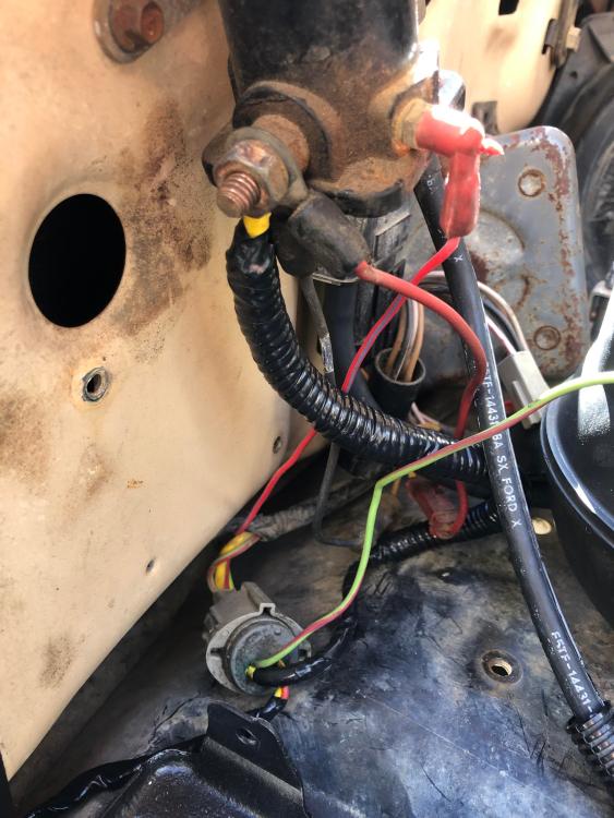
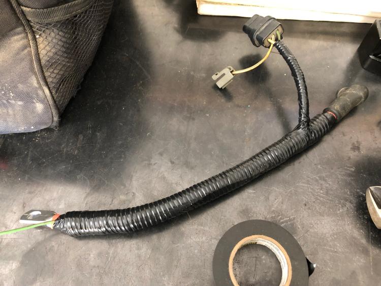
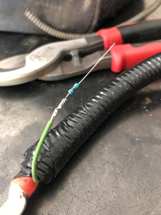
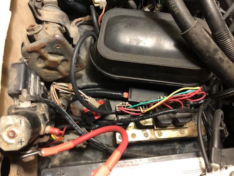
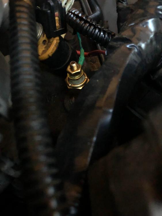
I then set about connecting the engine grounds and the sender wires. I first connected the wires at the gauges, I then loomed the wire and secured it under the dash.


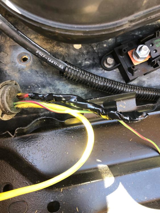
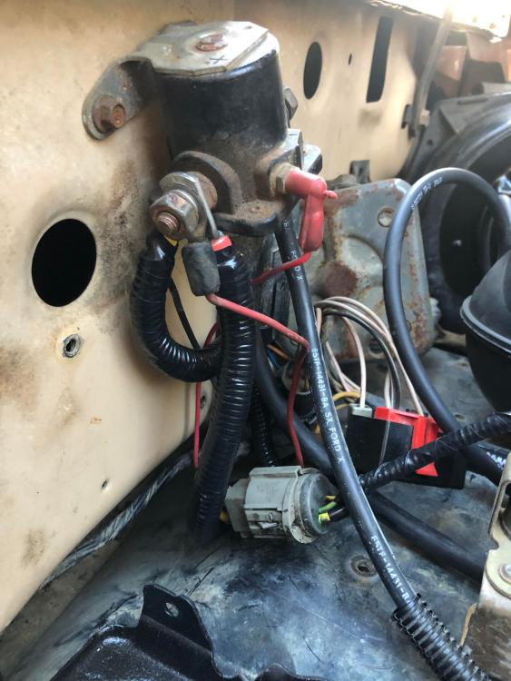
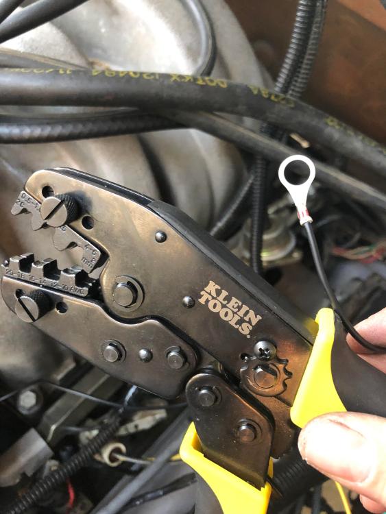
The loomed wire blends into the engine bay like it belongs. This was taken while crimping the ground wires. You can also see here that I relocated the ignition coil.


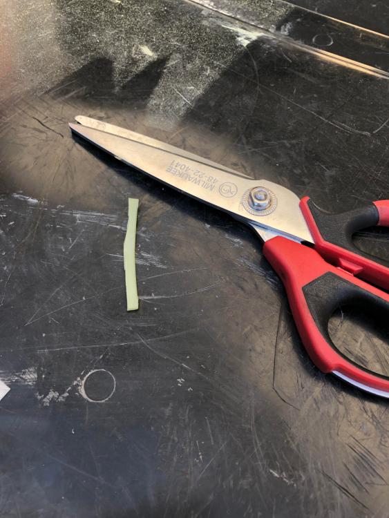
This tool and the crimping dies for non-insulated terminals was about $50 on Amazon. You need this tool. It's a ratcheting crimping tool. I prefer to use non-insulated terminals with heat shrink.


Grounds and senders connected.


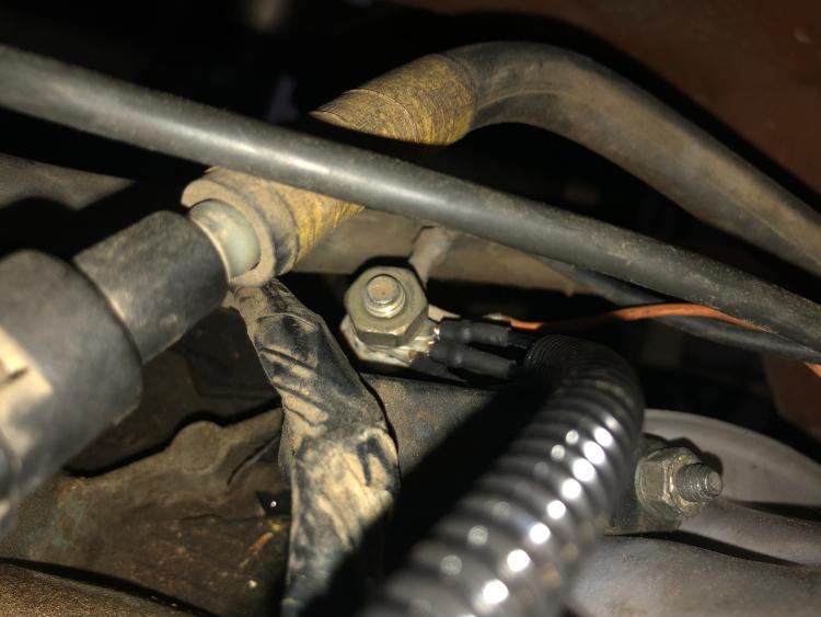
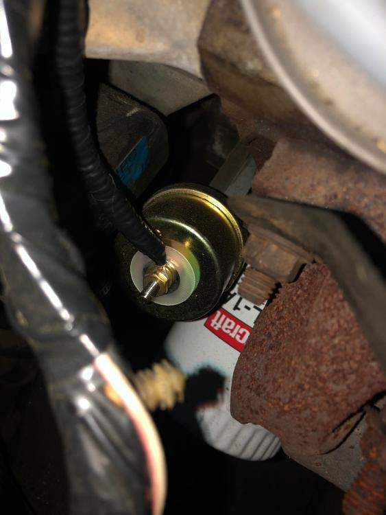
I happened to find these at O'Reilly. They were perfect for the grounds on the engine.


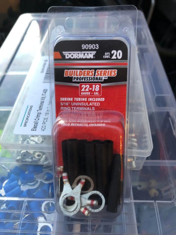
The end result. I'm super happy with these.


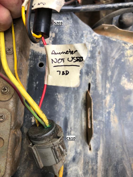
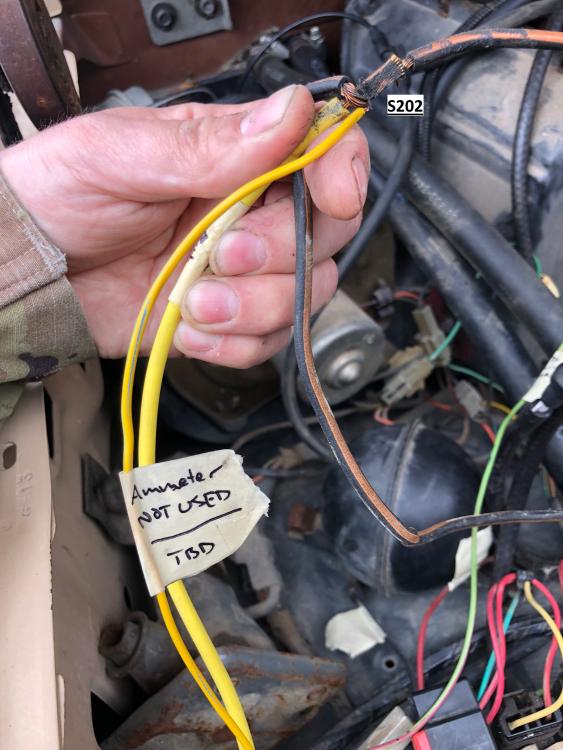
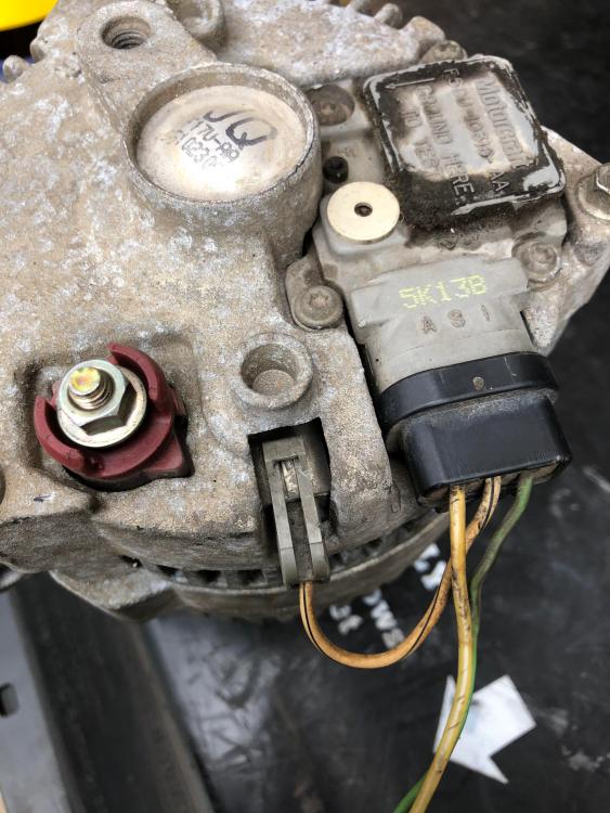
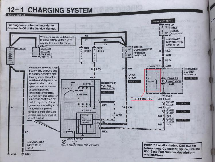
I'll post the 1G-to-3G part in a reply.
—John
1966 Mustang coupe; 1985 F-150 XLT Lariat; 1990 Mercury Grand Marquis; 1995 Mustang SVT Cobra
Reply | Threaded
Open this post in threaded view
|

Re: 1G-to-3G and serpentine swap, R134a conversion, and gauge install on my 1985 F-150

Giraffe
This post was updated on .
For the 3G swap, the first order of business was to label the sides of the solenoid and remove and label all the wires that were connected to it. Of course, you'll want to go with the PA Performance kit if you're wanting to keep your ammeter. I wasn't wanting to keep it and wanted a cleaner looking end product, so I decided to ditch the ammeter and do the wiring myself. This also allowed me to eliminate the external regulator entirely.

I made a note of what was what by comparing with the EVTM. I labeled everything accordingly. I also made notes of where I initially figured they would go.


It got a little more complicated when I unwrapped the alternator power wire. Ford put two splices in this harness to facilitate the ammeter. The EVTM and an annotated version of the changes I made is below.


Leftovers.


I also grabbed the connector off the donor vehicle. This makes wiring up the alternator a bit easier.


My goal was to approximate the charging system in my 1995 Mustang Cobra. Pay special attention to the 510 ohm resistor wired in parallel with the charge warning light. This is there to provide an excitation voltage to the alternator. Without this, the alternator won't charge. In most cases, Ford simply attached this resistor to the printed circuit board on the back of the instrument cluster. In my case, I soldered it in series with the light green/red wire to the alternator. Series is fine since there is no warning light with which to solder it in parallel.


Below are the changes I made.


And below is the end result. I'm well known for my exceptional MS Paint skills.


This end of the diagram doesn't change. With the setup above, the light green/red wire is connected to a switched 12V source just like with the 1995-spec charge circuit.


I wrapped up what was left of the ammeter wires and tucked them away for now. I couldn't bring myself to clip them off completely. This effectively isolates the ammeter from the system.


This is the yellow wire that was originally part of splice S202. It's originally connected directly to the alternator power feed. I crimped/heat shrunk on a terminal lug and attached it to the positive side of the solenoid. This effectively reconnects it to power direct from the alternator. The loom was just to make things look cleaner. A sharp eye will also notice that I swapped in the 1987+ battery tray.


After that, I built my alternator harness using 4 AWG welding cable and the junkyard harness. More loom.


This is the 510 ohm resistor that I soldered in series with the light green/red wire from the alternator "I" terminal. The resistor was kind of flimsy, so I used a piece of plastic to act as a strain relief. I then covered that with heat shrink.


The finished product with the charge wire connected to the solenoid.


The final product. I also installed the 1996+ vacuum reservoir. It took a while for me to settle on an arrangement that made sense and didn't leave everything looking too cluttered. At some point I will likely move or eliminate the emissions solenoids.


For the battery cables, I used the same 4 AWG cable. The clamps are Toyota clamps. I wanted something that allowed a bolt on connection that was a non-lead terminal.


—John
1966 Mustang coupe; 1985 F-150 XLT Lariat; 1990 Mercury Grand Marquis; 1995 Mustang SVT Cobra
Reply | Threaded
Open this post in threaded view
|

Re: 1G-to-3G and serpentine swap, R134a conversion, and gauge install on my 1985 F-150

ArdWrknTrk
Administrator
Hey John, that's an excellent little writeup about updating to the 3G alternator.  

Quite a few on this forum have been using the Rocket Man Innovations ammeter to voltmeter conversion so that there is better charge indication using their existing cluster. But with that you probably want to connect it to hot in run, or as Gary has done trigger a relay so he is reading voltage directly from the battery instead of from the far side of the ignition switch.

I'm also not so sure of the need for an in-line resistor for the excite wire.
It's primary purpose is to force enough current through the indicator lamp for it to glow, while still providing a backup if that bulb burns out.
That circuit is basically a comparator. Current flows through the bulb to the alternator until the alternator output rises high enough to balance the system and the lamp goes out.
I haven't heard of any alternator damage caused by wiring the (I) terminal directly.
 Jim,
Lil'Red is a '87 F250 HD, 4.10's, 1356 4x4, Zf-5, 3G, PMGR, Saginaw PS, desmogged with a Holley 80508 and Performer intake.
Too much other stuff to mention.
Reply | Threaded
Open this post in threaded view
|

Re: 1G-to-3G and serpentine swap, R134a conversion, and gauge install on my 1985 F-150

Rembrant
Excellent write up, well done! Great pictures too. I have a 1996 5.0 with original serpentine drive and 3G alternator that I'm installing into my 1952 pickup, so some of your info is very helpful to me. I'm planning on installed a triple gauge set like yours, so I'll check out the Stewart Warner gauges. I wanted them to be all electric like yours, so that's great info.


ArdWrknTrk wrote
I'm also not so sure of the need for an in-line resistor for the excite wire.
It's primary purpose is to force enough current through the indicator lamp for it to glow, while still providing a backup if that bulb burns out.
That circuit is basically a comparator. Current flows through the bulb to the alternator until the alternator output rises high enough to balance the system and the lamp goes out.
I haven't heard of any alternator damage caused by wiring the (I) terminal directly.
I too was wondering about that excite wire since I'll be installing the 5.0 with 3G in my pickup this summer. The previous setup in this truck had a little peanut style 194 bulb dangling under the dash as a means of exciting the GM alternator that was installed. I'll be installing all aftermarket gauges, so I wasn't sure what I needed to do with that green/red wire. If I can just wire it directly to the ignition and not even worry about a bulb or anything, then I guess I can just carry on. However, I believe the dash gauges I have been looking at DO have an alternator indicator light, so I wonder if I could use that....hmmm.
1994 F150 4x2 Flareside. 5.0 w/MAF, 4R70W, stock.
1984 F150 4X2 Flareside. Mild 302 w/ 5spd. Sold.
1980 F150 4X4 Flareside. 300i6 w/ 5spd. Sold in 2021.
1980 F100 4X2 Flareside. 351w/2bbl w/NP435. Sold in 1995

Reply | Threaded
Open this post in threaded view
|

Re: 1G-to-3G and serpentine swap, R134a conversion, and gauge install on my 1985 F-150

ArdWrknTrk
Administrator
A bulb should be fine Cory.
An LED won't sink enough power to tickle the 3G alternator.
 Jim,
Lil'Red is a '87 F250 HD, 4.10's, 1356 4x4, Zf-5, 3G, PMGR, Saginaw PS, desmogged with a Holley 80508 and Performer intake.
Too much other stuff to mention.
Reply | Threaded
Open this post in threaded view
|

Re: 1G-to-3G and serpentine swap, R134a conversion, and gauge install on my 1985 F-150

Rembrant
ArdWrknTrk wrote
A bulb should be fine Cory.
An LED won't sink enough power to tickle the 3G alternator.
But if I don't want to use a bulb, I can just use the 510 ohm resistor then, right? Or should one use both like in the Ford diagram? Since I won't have a factory gauge or bulb to wire to, I'll have to install something else...and I'd like it to be at least somewhat pleasing to the eye (as opposed to the 194 bulb that was dangling under the dash previously lol).
1994 F150 4x2 Flareside. 5.0 w/MAF, 4R70W, stock.
1984 F150 4X2 Flareside. Mild 302 w/ 5spd. Sold.
1980 F150 4X4 Flareside. 300i6 w/ 5spd. Sold in 2021.
1980 F100 4X2 Flareside. 351w/2bbl w/NP435. Sold in 1995

Reply | Threaded
Open this post in threaded view
|

Re: 1G-to-3G and serpentine swap, R134a conversion, and gauge install on my 1985 F-150

ArdWrknTrk
Administrator
As stated ^^^ way up there, you don't need anything but the wire Cory.
I DO like your truck clean and simple.
Though I can understand the PO's wanting some charge indication.


 Jim,
Lil'Red is a '87 F250 HD, 4.10's, 1356 4x4, Zf-5, 3G, PMGR, Saginaw PS, desmogged with a Holley 80508 and Performer intake.
Too much other stuff to mention.
Reply | Threaded
Open this post in threaded view
|

Re: 1G-to-3G and serpentine swap, R134a conversion, and gauge install on my 1985 F-150

Rembrant
ArdWrknTrk wrote
As stated ^^^ way up there, you don't need anything but the wire Cory.
I DO like your truck clean and simple.
Though I can understand the PO's wanting some charge indication.
Got it! Thanks Jim, and thanks John for the great post with all the pics (Sorry for the hijack!).
1994 F150 4x2 Flareside. 5.0 w/MAF, 4R70W, stock.
1984 F150 4X2 Flareside. Mild 302 w/ 5spd. Sold.
1980 F150 4X4 Flareside. 300i6 w/ 5spd. Sold in 2021.
1980 F100 4X2 Flareside. 351w/2bbl w/NP435. Sold in 1995

Reply | Threaded
Open this post in threaded view
|

Re: 1G-to-3G and serpentine swap, R134a conversion, and gauge install on my 1985 F-150

Gary Lewis
Administrator
In reply to this post by ArdWrknTrk
Wonderful write ups!  Very well done!  Neat and clean.

But I agree with Jim about the resistor.  The vehicles with warning lights did use a resistor in case the bulb burned out, but the vehicles w/o didn't have the resistor.  So it isn't needed.

HOWEVER, another member just had a start/no-stop situation and it appears he was using a non-Ford alternator that was feeding power back into the system via that excite wire.  In his case he put a diode in that wire and solved the problem.  But it is possible that a bulb would have sufficed.  And the resistor probably will as well.
Gary, AKA "Gary fellow": Profile

Dad's: '81 F150 Ranger XLT 4x4: Down for restomod: Full-roller "stroked 351M" w/Trick Flow heads & intake, EEC-V SEFI/E4OD/3.50 gears w/Kevlar clutches
Blue: 2015 F150 Platinum 4x4 SuperCrew wearing Blue Jeans & sporting a 3.5L EB & Max Tow
Big Blue: 1985 F250HD 4x4: 460/ZF5/3.55's, D60 w/Ox locker & 10.25 Sterling/Trutrac, Blue Top & Borgeson, & EEC-V MAF/SEFI

Reply | Threaded
Open this post in threaded view
|

Re: 1G-to-3G and serpentine swap, R134a conversion, and gauge install on my 1985 F-150

Giraffe
"Required" may be too strong a word. In all fairness, I'm not an electrical engineer. I've forgotten most of what I learned when I took an electronic principles course fifteen years ago. That said, I decided to include the resistor because everything I was able to find regarding it indicated that it was required.

I decided to put it in the circuit since I'm sure it can't hurt.

Here's a few more pictures in daylight. I just got this done last night. One thing I forgot to mention is that the 1996 F150 (EEC-V) that I pulled the brackets from also had an idler pulley instead of a smog pump. Nice little bonus. The intake tube and air box are from the same truck. It's nice to have the MAF sensor in case I decide to use it in the future.


The gauge ground and sender wiring. It's the loom that has the y in it. One leg goes to the engine/firewall ground while the other was routed underneath the coil bracket.


—John
1966 Mustang coupe; 1985 F-150 XLT Lariat; 1990 Mercury Grand Marquis; 1995 Mustang SVT Cobra
Reply | Threaded
Open this post in threaded view
|

Re: 1G-to-3G and serpentine swap, R134a conversion, and gauge install on my 1985 F-150

ArdWrknTrk
Administrator
That's a nice, clean install of the ground harness.  

Cory (Rembrandt) just figured out the polygroove belt routing for the Windsor he's installing in his '52.
While Bill (Vose) and Gary have quite a bit of information on integrating EEC-V + OBD-II with Bullnose era trucks posted here on the site.

You might find some interest in that if you're considering MAF SEFI for your '85
 Jim,
Lil'Red is a '87 F250 HD, 4.10's, 1356 4x4, Zf-5, 3G, PMGR, Saginaw PS, desmogged with a Holley 80508 and Performer intake.
Too much other stuff to mention.
Reply | Threaded
Open this post in threaded view
|

Re: 1G-to-3G and serpentine swap, R134a conversion, and gauge install on my 1985 F-150

Gary Lewis
Administrator
That's a really clean installation of everything.  And that may be the best for aftermarket gauges that I've seen.  

As for EEC-V, I'm approaching the goal post on this quest.  But it isn't for the faint of heart.  If you got all the harnii from the donor truck, and I sure hope you did, it shouldn't be too bad.  The problem is that the ECU on the donor truck is going to be in the driver's kick panel, and yours is just to the left of where you put the gauges.  So you'll either have to modify the truck to get the computer where the harness will stretch, or extend the harness to where your computer is now.

I'm doing the latter and it is really fiddly.  But in my case I think it'll be worth it since I'm coming from a carb to a sequential fuel injection system using a mass air sensor.  In your case, if you don't change the cam, intake, or exhaust you might not see much difference to your speed density/bank fire system.
Gary, AKA "Gary fellow": Profile

Dad's: '81 F150 Ranger XLT 4x4: Down for restomod: Full-roller "stroked 351M" w/Trick Flow heads & intake, EEC-V SEFI/E4OD/3.50 gears w/Kevlar clutches
Blue: 2015 F150 Platinum 4x4 SuperCrew wearing Blue Jeans & sporting a 3.5L EB & Max Tow
Big Blue: 1985 F250HD 4x4: 460/ZF5/3.55's, D60 w/Ox locker & 10.25 Sterling/Trutrac, Blue Top & Borgeson, & EEC-V MAF/SEFI

Reply | Threaded
Open this post in threaded view
|

Re: 1G-to-3G and serpentine swap, R134a conversion, and gauge install on my 1985 F-150

Giraffe
Gary Lewis wrote
That's a really clean installation of everything.  And that may be the best for aftermarket gauges that I've seen.  

As for EEC-V, I'm approaching the goal post on this quest.  But it isn't for the faint of heart.  If you got all the harnii from the donor truck, and I sure hope you did, it shouldn't be too bad.  The problem is that the ECU on the donor truck is going to be in the driver's kick panel, and yours is just to the left of where you put the gauges.  So you'll either have to modify the truck to get the computer where the harness will stretch, or extend the harness to where your computer is now.

I'm doing the latter and it is really fiddly.  But in my case I think it'll be worth it since I'm coming from a carb to a sequential fuel injection system using a mass air sensor.  In your case, if you don't change the cam, intake, or exhaust you might not see much difference to your speed density/bank fire system.
Unfortunately, I didn't get the entire harness from the truck. My eventual plan for this truck when it comes to the computer is to swap to a megasquirt setup. The truck I pulled the brackets from is long gone. If I was looking to do a factory EEC-V swap, I would have liked to have had the entire 1996-spec harness. I did pull the 1996-specific timing cover with the crank sensor, though.
—John
1966 Mustang coupe; 1985 F-150 XLT Lariat; 1990 Mercury Grand Marquis; 1995 Mustang SVT Cobra
Reply | Threaded
Open this post in threaded view
|

Re: 1G-to-3G and serpentine swap, R134a conversion, and gauge install on my 1985 F-150

ArdWrknTrk
Administrator
THAT'S dedication, to get down to the timing cover in a JY!

I'm glad you managed to get it in one piece.
99% of them are badly corroded and stuck to the bolts by this point.
 Jim,
Lil'Red is a '87 F250 HD, 4.10's, 1356 4x4, Zf-5, 3G, PMGR, Saginaw PS, desmogged with a Holley 80508 and Performer intake.
Too much other stuff to mention.
Reply | Threaded
Open this post in threaded view
|

Re: 1G-to-3G and serpentine swap, R134a conversion, and gauge install on my 1985 F-150

Gary Lewis
Administrator
Yes, that's dedication!

But Megasquirt is another EFI system that I don't think will have much benefit if you don't plan to make significant changes to the engine.  Having said that, if you do plan to make significant changes the SD system won't like that, so something's gotta change.
Gary, AKA "Gary fellow": Profile

Dad's: '81 F150 Ranger XLT 4x4: Down for restomod: Full-roller "stroked 351M" w/Trick Flow heads & intake, EEC-V SEFI/E4OD/3.50 gears w/Kevlar clutches
Blue: 2015 F150 Platinum 4x4 SuperCrew wearing Blue Jeans & sporting a 3.5L EB & Max Tow
Big Blue: 1985 F250HD 4x4: 460/ZF5/3.55's, D60 w/Ox locker & 10.25 Sterling/Trutrac, Blue Top & Borgeson, & EEC-V MAF/SEFI

Reply | Threaded
Open this post in threaded view
|

Re: 1G-to-3G and serpentine swap, R134a conversion, and gauge install on my 1985 F-150

Rembrant
In reply to this post by ArdWrknTrk
ArdWrknTrk wrote
THAT'S dedication, to get down to the timing cover in a JY!

I'm glad you managed to get it in one piece.
99% of them are badly corroded and stuck to the bolts by this point.
That sure IS dedication, I agree. Once those bolts are corroded in the aluminum, the water pump removal is tough enough without getting into the timing cover.

I know it's too late now, but there is a way around having to replace the old CW carbed timing cover when switching to serpentine drive. Install a water pump from a 1986 Mustang 5.0 GT. I guess because Ford started using the serpentine drive system on the 5.0 when it was still carbed (or still used the old timing cover) they made a water pump with round ports instead of the D shaped ports. The pump with the round ports can be installed on either CW or CCW timing cover, and they're physically the same as all the other water pumps otherwise. I have one of these on my 5.0 now as I was planning to run an old carbed cover, but I ended up with an EFI timing cover anyway. What's his name put me on to this?...Who is the member on here that works at a Ford dealer in Oregon or Washington?...Earl?


1994 F150 4x2 Flareside. 5.0 w/MAF, 4R70W, stock.
1984 F150 4X2 Flareside. Mild 302 w/ 5spd. Sold.
1980 F150 4X4 Flareside. 300i6 w/ 5spd. Sold in 2021.
1980 F100 4X2 Flareside. 351w/2bbl w/NP435. Sold in 1995

Reply | Threaded
Open this post in threaded view
|

Re: 1G-to-3G and serpentine swap, R134a conversion, and gauge install on my 1985 F-150

Rembrant
In reply to this post by Giraffe
Hey Giraffe,

Where did you get the triple gauge set? Have a link or a part number by chance?
1994 F150 4x2 Flareside. 5.0 w/MAF, 4R70W, stock.
1984 F150 4X2 Flareside. Mild 302 w/ 5spd. Sold.
1980 F150 4X4 Flareside. 300i6 w/ 5spd. Sold in 2021.
1980 F100 4X2 Flareside. 351w/2bbl w/NP435. Sold in 1995

Reply | Threaded
Open this post in threaded view
|

Re: 1G-to-3G and serpentine swap, R134a conversion, and gauge install on my 1985 F-150

Giraffe
In reply to this post by Rembrant
Rembrant wrote
ArdWrknTrk wrote
THAT'S dedication, to get down to the timing cover in a JY!

I'm glad you managed to get it in one piece.
99% of them are badly corroded and stuck to the bolts by this point.
That sure IS dedication, I agree. Once those bolts are corroded in the aluminum, the water pump removal is tough enough without getting into the timing cover.

I know it's too late now, but there is a way around having to replace the old CW carbed timing cover when switching to serpentine drive. Install a water pump from a 1986 Mustang 5.0 GT. I guess because Ford started using the serpentine drive system on the 5.0 when it was still carbed (or still used the old timing cover) they made a water pump with round ports instead of the D shaped ports. The pump with the round ports can be installed on either CW or CCW timing cover, and they're physically the same as all the other water pumps otherwise. I have one of these on my 5.0 now as I was planning to run an old carbed cover, but I ended up with an EFI timing cover anyway. What's his name put me on to this?...Who is the member on here that works at a Ford dealer in Oregon or Washington?...Earl?


That's great information! In my case, it's better that I switched to the later timing cover since the original timing change was in bad need of replacement. I probably had more than a half inch of slop in the original single-roller chain. Not to mention it was the chain with plastic teeth on the cam gear. I replaced it with a Cloyes Street true double roller timing chain set.

Getting down to the timing cover in a junkyard isn't too difficult. It just requires the right tools. A 1/2" drive socket set, an electric impact, and a harmonic balancer removed work wonders.
—John
1966 Mustang coupe; 1985 F-150 XLT Lariat; 1990 Mercury Grand Marquis; 1995 Mustang SVT Cobra
Reply | Threaded
Open this post in threaded view
|

Re: 1G-to-3G and serpentine swap, R134a conversion, and gauge install on my 1985 F-150

Giraffe
In reply to this post by Rembrant
Rembrant wrote
Hey Giraffe,

Where did you get the triple gauge set? Have a link or a part number by chance?
I pieced it together.

The panel is from VDO: https://www.summitracing.com/parts/vdo-240029

I would agree with some of the lower reviews on it. It is a bit flimsy in that the gauge clamps put indentations in the front of the panel. You'd have to look really close to see it, but it's still kind of annoying. Not too bad for less than $20.

The gauges are all Stewart Warner. They're all assembled in Mexico.

Oil pressure: https://www.summitracing.com/parts/sww-284ae
Water temp: https://www.summitracing.com/parts/sww-284af
Voltmeter: https://www.summitracing.com/parts/sww-284h

I really like these gauges. My only gripe is that the needles don't move fluidly. Sometimes I'll have to tap the gauge a little bit to get the needle to move. They seem to be pretty accurate, though. You can tell when the thermostat opens just by looking at the temp gauge.

The senders are both electronic from Stewart Warner.

Oil: https://www.summitracing.com/parts/sww-279a
Water: https://www.summitracing.com/parts/sww-280ec
—John
1966 Mustang coupe; 1985 F-150 XLT Lariat; 1990 Mercury Grand Marquis; 1995 Mustang SVT Cobra