Search Forum
Battery Cable Sizing

123
123

|
Got it, that makes sense. If you have it isolated from the main to run like a house battery in a RV or whatever terminology applies lol.
BUT this should not be a big deal if 1) your alternator is sufficient to charge both batteries, and 2) you have identical batteries in parallel. When you have batteries with different stats the stronger battery will attempt to charge the other battery to balance out the circuit. If the main is the powerhouse in this case then it will drain itself to charge the auxiliary.
1986 F-150|Standard Cab|4x2|300Six|C6Transmission w/3.08 rear|Name:TBD
2021 Ranger XLT Super Crew |
|
Administrator
|
You are correct - if the truck is running. Gary has the use case(s) correct. It's when the truck isn't running that the isolator allows you to use the aux without worry.
Because they will be joined shortly after the truck starts and ideally stay that way until the truck is killed, they will be a matched set to avoid the issue you mentioned.
Scott
'Camano' 1986 F250 Supercab XLT Lariat 460/C6 'Chanute' 1980 F350 C&C 400/NP 435 - Gin Pole But there ain't nothin' wrong with the radio |
|
|
In reply to this post by Gary Lewis
<quote author="Gary Lewis">
This makes sense to me if you are running a large draw with the key off to protect the main battery from getting too low to start the truck, but if the truck is running, with a sufficient amperage alternator it should keep the batteries charged enough to power all the auxiliary items without having the engine to rev up to compensate. Unless I am just that tired and missing something that requires me to look at a schem of what he is talking about to spark that "Ah-ha" moment. In the RV I had there was a battery isolation switch so when you were parked, engine off, the house battery was manually disconnected from the charge circuit. When you were up and running, you put the house batter back in the circuit and the alternator charged the main and house batteries, which is in essence what using a relay to put them in parallel would do automatically and for sure would be more ideal route to go if you planned on using batteries of differing capacities or with the engine of. That also makes sense why I was confused because like you quoted from my original post when I have seen people wire batteries directly in parallel then run a bunch of wires tapped of the (+) battery post trying to just drain that specific battery, which makes no sense. In that type of set up one would be better served taking a the same gauge wire as the positive to a fuse block then running an appropriately gauged wire to each device from the block.
1986 F-150|Standard Cab|4x2|300Six|C6Transmission w/3.08 rear|Name:TBD
2021 Ranger XLT Super Crew |
|
|
In reply to this post by kramttocs
I'm tracking now lol. I was confused on the original intent.
1986 F-150|Standard Cab|4x2|300Six|C6Transmission w/3.08 rear|Name:TBD
2021 Ranger XLT Super Crew |
|
|
In reply to this post by 85lebaront2
Probably because hot/cold welded joints are more stable and less susceptible to heat. If you have a tin coated copper terminal or wire soldered to another tin coated wire you have copper, tin, silver or lead all in the joint and they all have different thermal and conductive properties contracting and expanding at different rates which can lead to failure. Second a weld like that can be done quickly with repeatable quality vs a solder joint. Speed with quality is a key driver in manufacturing. The solder we use has even been idiot proofed (raychem solder sleeves) you take your shields, or your ground wire and zap it with a IR gun it melts and you move on after you make sure the filet flows, there is no excessive tinning up the shield and the the sleeve isn't burnt. you cant over or under solder, make the shield/wire brittle by wicking too much up it etc.
1986 F-150|Standard Cab|4x2|300Six|C6Transmission w/3.08 rear|Name:TBD
2021 Ranger XLT Super Crew |
|
Administrator
|
In reply to this post by Danny G
Your attention to detail and understanding of the matter really shows!  The military certainly works in the most extreme environments. From the bottom of the sea to the top of the world, and beyond our atmosphere. (radiation in space is especially harsh) And EVERYTHING is mission critical! WAY back in the day my father used to design and prototype electronics for a bunch of military contractors and 'agencies'.... Norden, Raytheon, Sikorsky, Hamar, Perkin Elmer, NASA, you name it, easy of the Mississippi.
Jim,
Lil'Red is a '87 F250 HD, 4.10's, 1356 4x4, Zf-5, 3G, PMGR, Saginaw PS, desmogged with a Holley 80508 and Performer intake. Too much other stuff to mention. |
|
|
This post was updated on .
In reply to this post by kramttocs
Are you wiring your auxiliary items off the battery positive or the isolation relay. If wired like the schematic from Ford, that relay goes hot in accy/run connecting the aux in parallel whether the engine is running or not. I think this may been what Steve was hinting at with key off time. So basically if you stereo requires you to turn the key to accy, your not protecting the main battery. Looks like the aux was originally designed to run lights with the keys out of ignition. ***EDIT *** Added thought, It may actually be better to isolate the main battery while the key is in ACCY mode, then when the key is turned to run, juice that relay pulling the main back into the loop to start/run the engine. That way if you turn the key to ACCY you can run the stereo off the aux battery and protect the main from draining. 
1986 F-150|Standard Cab|4x2|300Six|C6Transmission w/3.08 rear|Name:TBD
2021 Ranger XLT Super Crew |
|
|
In reply to this post by ArdWrknTrk
That sounds like a pretty sweet gig. My goal is to move over to the space side of the house with my company, just waiting for the right opening.
1986 F-150|Standard Cab|4x2|300Six|C6Transmission w/3.08 rear|Name:TBD
2021 Ranger XLT Super Crew |
|
Administrator
|
I wish you luck.
There is certainly a lot of room to grow, and with cheaper access to space the growth looks exponential.
Jim,
Lil'Red is a '87 F250 HD, 4.10's, 1356 4x4, Zf-5, 3G, PMGR, Saginaw PS, desmogged with a Holley 80508 and Performer intake. Too much other stuff to mention. |
|
|
This post was updated on .
OK someone double check my work here on isolating the main vs the aux for wanting to run a stereo etc.
If you use the "Run" part of the ingition to actuate the a relay connecting the main battery back into the power circuit, this means you can put the ignition in ACCY and run everything, with the engine off, from the auxiliary battery without risking the main battery. In the pictures below, putting this relay anywhere between splice S208 and the starter relay would accomplish this. Then you would take power from the "Run" signal either at S401 or S216 to the relay to bring the main battery back into the circuit. If you do this between splice S101 and the starter relay it would allow the auxiliary battery run lights as well while having the added bonus of allowing your ammeter/voltmeter to show drain/current voltage of the main battery. Even if your aux was on its last legs, in the "Start" position it is only responsible to activate the starter relay, the starting power to the starter would still come from the main battery. Heck while your at it you could whack out all these fuse links and install a fuse box. 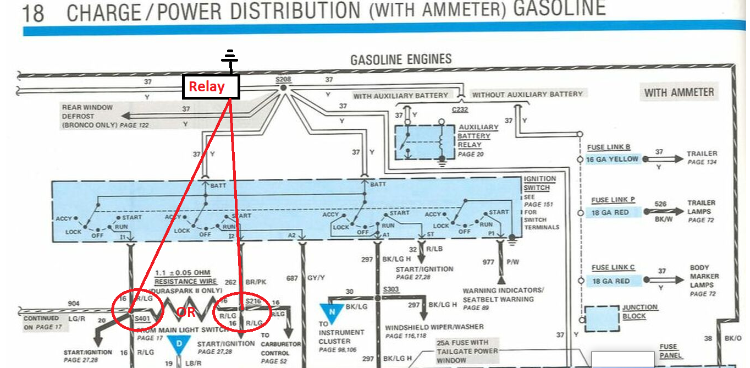 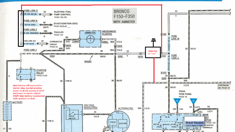
1986 F-150|Standard Cab|4x2|300Six|C6Transmission w/3.08 rear|Name:TBD
2021 Ranger XLT Super Crew |
|
Banned User
|
This post was updated on .
In reply to this post by Danny G
That's exactly why that experience isn't directly-applicable to common vehicles like these old trucks. The vibrations from fan turbojet engines will fatigue a solder joint on a wire that has a few unsupported inches because it will make as many high-amplitude oscillations in 1 flight as these trucks experience in a lifetime. So the same solder joint on an unsupported wire or cable on these trucks will last the rest of their lives (which can't be another 30 years, given the way laws are going regarding gasoline-powered vehicles). If you HAVE those, then you might want to use them. But they're VASTLY more expensive than a propane torch & a roll of solder. And once you crimp one, that's it - if you goof it, or need to change something, the crimped connector AND the wire inside it are trash. With solder, you can re-do it any time you feel the need, without losing any wire OR the connector. Some people claim that solder is inferior to crimping because, if the battery terminal gets hot, the wire can fall out. I see that as a BIG ADVANTAGE. If either of my battery terminals ever gets hot enough to melt solder, I WANT the cable to fall out before the battery explodes. But being such a complete mechanical AND electrical connection, it's very unlikely. Even if there was THAT much resistance between the post & terminal (which is exactly as likely with a terminal crimped onto its wire), the soldered joint will conduct that heat into the (heavy) cable much better than the crimp will, thereby dissipating the heat before the temperature gets that high. The solder (when done correctly) seals the joint from air, water, and battery acid, so it never corrodes at all. A crimp might, but you can only know that by destructive inspection, or when it fails. The alternator CAN put out more; it doesn't ALWAYS put out more. And even when it's putting out its max, that has no effect on how much current the aux.batt. is drawing. If the aux.batt. is going to draw 120A, it'll do that regardless of what alternator is installed, or what that alt. is putting out. If it can't get it from the alt, it'll get it from the other battery. So don't worry about it. Just design & build your circuits properly, and you can run any alternator. If it's too small, it'll burn out, but that won't affect your circuits. If it's oversized, it won't ever reach its max output, and everything will still be fine. That's a popular mythconception. That happens if the VOLTAGES are different, which is exactly as likely to happen between "identical" batteries of the same age, as it is between any two Lead-acid batteries (regardless of size, ratings, or age). But since the batteries aren't actually in (constant) parallel, it's moot. You can run batteries of different chemistries (with intrinsically-different voltage) without problems. You're talking about a film of alloy a few microns thick with a difference in coefficient of thermal expansion on the order of 10^-7; it will never experience enough temperature change to induce enough strain to exceed its yield strength. Maybe on a deep-space probe; but never on an old pickup. Why would you ever take it OUT? That makes your primary battery's state-of-charge dependent on this new relay. And you won't know the relay has failed until it's too late. Keep the critical circuits reliable. ...be much more-complicated & failure-prone than just moving those lighting circuits to the aux.batt. side of the (ONE) aux.batt. relay. It already does. You're just complicating the circuit, and then adding more complications to make some things work the way they did before. If you want a voltmeter for the aux.batt., add one. That's the purpose of the 2-color LED in my diagram. It's simpler & cheaper than adding a voltmeter, and draws less current. The way my diagram shows the simple additional switch, either battery can be used for cranking. Bad idea. Fuses don't work the same way as fusible links, and the circuit design is different for them. You should never replace one with the other, unless you're prepared to re-engineer the affected circuits. |
|
|
There is merit in both, but my point is calling solder superior in longevity and connection, bottom line end of story to a crimp or swage is not a true statement. Granted were talking different stress environments, that just enforces the later equipment must be superior in durability. I have a feeling if we tore down a modern vehicle solder joints are also slim to non though. Those hydraulic ones that put out high psi are for serious wiring not on applicable to automobiles (640v), but also is for a very limited use on aircraft as well. There are hundreds of miles of wire and thousands of connectors, terminals and splices all done with hand tools most of which that can be had for reasonable prices to the lay person(under $100). Mechanical splices are then sealed with environmental shrink which keeps out the elements and provides a strain relief. The down side vs solder is you need a different die or tool per type of connection. Where as you pointed out a nice bench unit, a torch, and a $5 roll of solder, maybe a solder sucker and a few heat sinks and you are set to solder anything.
Both mechanical and solder joints will have issues if done wrong, solder has the advantage of sparing some wire but if your heating wire up to the point of causing a solder failure, you may need to think about the integrity of that wire to begin with. An unskilled person re-soldering the same wire over and over again may cause a lot of solder to wick up the wire making it brittle and end up needing to replace or splice in a new run anyway (something a heat sink that they didn't use could have helped with to an extent) or they didn't clean the wire before soldering and are having issues getting it to hang. With crimps, clean fresh wire is key for good cold welds, if its corroded and you crimp it with too much or too little force you will end up with something that just doesn't work out in the end. I think a lot of the bad name for crimping comes from guys using any old tool to make the crimp (like needle nose pliers). Or not sizing the crimp to the the wire; for example your wire should match the diameter of the crimp as closely as possible, this means you need to add a stub wire or double your strip and fold the conductor over to take up more space in the crimp barrel to properly do the job. I guess the answer to which you should use, ends up being like it is for a lot of things: Whatever you are comfortable with, works within the given perimeters and can properly accomplish the task at hand to a level that you are satisfied with.
1986 F-150|Standard Cab|4x2|300Six|C6Transmission w/3.08 rear|Name:TBD
2021 Ranger XLT Super Crew |
|
|
In reply to this post by Steve83
Steve, wiring the circuit the way it is in the ford spec is fine for just running lights as you pointed out, and as Ford originally had it. The lights don't draw power constantly from the aux battery, only when switched on.
But the OP wants to run a stereo system. Last I checked the radio only gets power when in the RUN or ACCY position. Which means he can have all his equipment on that aux battery all day long but it is useless until he turns the key, which pulls the main battery back in and defeats the purpose all together. He would have to rewire the system so the stereo head unit gets power from the aux battery along with the rest of his equipment, which would leave it in a constant on state when the key is out of the ignition unless he wires in a switch to kill the power to the stereo. If your diagram shows that switch and that's whats going down cool, I didn't look at your diagram, couldn't pull it up (security on my computer).
1986 F-150|Standard Cab|4x2|300Six|C6Transmission w/3.08 rear|Name:TBD
2021 Ranger XLT Super Crew |
|
Administrator
|
Just to clarify - I said amp and sub
 I am keeping the headunit factory wired. That's why I asked the (I would consider odd) question about the yellow wire - I am wanting to keep as much factory as possible so it's easy to eliminate my add ons if needed for whatever unknown reason and the core components will still function. I am keeping the headunit factory wired. That's why I asked the (I would consider odd) question about the yellow wire - I am wanting to keep as much factory as possible so it's easy to eliminate my add ons if needed for whatever unknown reason and the core components will still function.
Not saying it's a perfect system but it should do what I want. Anyways, carry on. While it has digressed from just cable sizes, it's an interesting read/discussion. 
Scott
'Camano' 1986 F250 Supercab XLT Lariat 460/C6 'Chanute' 1980 F350 C&C 400/NP 435 - Gin Pole But there ain't nothin' wrong with the radio |
|
|
This post was updated on .
In reply to this post by Steve83
Bad idea. Fuses don't work the same way as fusible links, and the circuit design is different for them. You should never replace one with the other, unless you're prepared to re-engineer the affected circuits. OK first quote is somewhat of typo and you would have notice that if you looked at the diagram. It shows the main battery still directly connected to the alternator, so the state of charge is NOT dependent on the "new relay". The main battery is disconnected from the auxiliary systems (radio lights etc) not the charge circuit. In that set up both batteries can be used for cranking the vehicle as well. The stereo should have two 12v inputs one for power one that keeps all your settings etc and another that is added when the key is in ACCY/Run. In order to run the stereo and isolate the main battery while the engine is off either you need to put in a relay that isolates the main battery (which pretty much needs 1 additional wire) or you need to rewire your truck so the stereo no longer comes on with the ignition but is powered directly from the auxiliary meaning both 12v inputs are going to your aux battery post. Then to make sure that doesn't drain your auxiliary because its constantly on it needs to be switched.That means every time you get in and start your truck your stereo is off and you have to flip a secondary switch to activate your radio. I would rather just turn my key then add more switches in my cab. I have a friend that does audio tell me they do just this adding a 200amp solenoid that isolates the main battery and alternator from the rest of the vehicle. Then the owner can set the key to ACCY to run the stereo off the aux. He said the only time they have ever run the stereo completely off the aux with a switch to power the head unit on and off was for show cars where they needed a couple hours of run time without leaving he key in the car. And in that set up they always added an extra relay to prevent backfeed. Also I understand fusible links down work the same way as normal fuses work (slow burn vs instant pop) so maybe I should have reworded this but. You can still whack out all the wired fuse links and put in a fuse block with blade style fusible links, or terminal style fusible links like bussmann makes vs fusible link wire. If you ever get in trouble those are easier to keep in the glove box then the tools needed to replace fusible link wire. 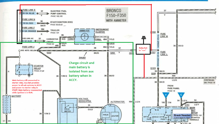 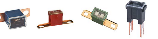
1986 F-150|Standard Cab|4x2|300Six|C6Transmission w/3.08 rear|Name:TBD
2021 Ranger XLT Super Crew |
|
|
In reply to this post by kramttocs
I guess I am not understanding what you are trying to do with sub, amp, winch and trailer wiring. If wired as factory for the head unit, you don't get any stereo until the key is in either accy or run. And at that point, even if the sub and amp are attached to the auxiliary battery you hooked it back in parallel with the main battery. Unless your not doing the aux battery relay like in Gary's schematic and are wiring it so in ACCY the relay is open and the aux battery powers the sub and amp, while the main battery powers the head unit, then in RUN the relay closes adding the aux back in parallel and charging it. That may be what has me twisted, I was thinking your wired like this and just adding the amp/sub to the aux (+): 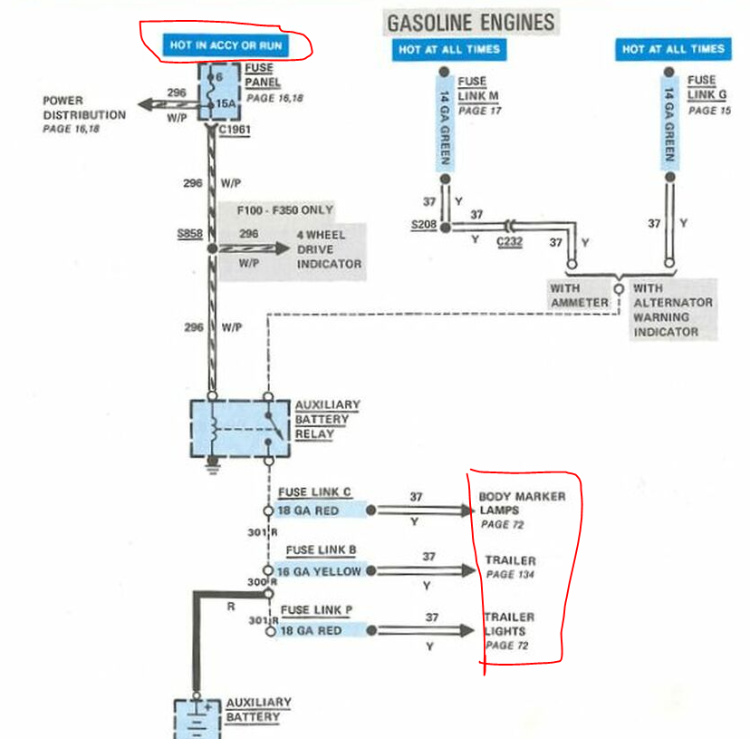
1986 F-150|Standard Cab|4x2|300Six|C6Transmission w/3.08 rear|Name:TBD
2021 Ranger XLT Super Crew |
|
|
In reply to this post by Steve83
Meant to touch on this to clear this up. I think we are on the same page. These are two different thoughts. Electromotive force and potential difference causes charge or discharge to happen. Energy flows to the lower potential. When you have batteries of different stats IE one at 12 volts and one at 6 volts the 12(stronger battery) will charges the 6 so long as the the amp hours (capacity) allow it to. If thought of as two object pushing against each other 12>6. Amp hours Are not independent of voltage. In the case of unwanted drain. If a 12v battery is dead, has a volt reading of 10.5 volts and has little energy storage compared to a fully charged 12v battery putting out say 12.3v and having a toped off 2ah capacity, the dead battery has less potential. Potential difference says the higher voltage and higher capacity of the fully charged battery will discharge into the dead one. I can't remember if that applies to only series or if it applies in parallel too.
1986 F-150|Standard Cab|4x2|300Six|C6Transmission w/3.08 rear|Name:TBD
2021 Ranger XLT Super Crew |
|
Banned User
|
This post was updated on .
I guess so. I've been talking about '80s pickup trucks. You're probably right. But that's not what we're discussing. We're talking about how a hobbyist mechanic working on his own antique vehicle can produce a reliable joint in a battery cable. And I'm also talking about how he can repair or modify it later as his needs change. Not really. Any plastic is VASTLY more-elastic than Copper. So the wire inside will strain long before the plastic shrink around the adhesive around the soft insulation ever takes up a significant load. When what you say is different from what you draw, I can't know which one you meant. I guessed the words because what you drew is very complicated and failure-prone, relying on several new parts & MANY new connections. It's a lot more complex than that. It's like the difference between taking an antihistamine for an allergy, and taking adrenaline/epinephrine. They accomplish the same goal, but not the same way; so you can't simply substitute one for the other. You & I might know how, but many others following this thread could create dangerous situations if they attempt to convert a fusible-link-protected circuit to a fuse-protected circuit. That's why I'm discouraging it. I don't think ANYONE is ever going to try to parallel a 12V cranking battery with a 6V aux.batt. in a 12V vehicle. That would almost instantly cause at least one of them to explode. What most people mean when they talk about "unmatched batteries" is two 12V batteries with at least one difference from this list: - brand - model/construction/chemistry - production date - group size - CCA rating - RC/RM/Ah rating - history of use (e.g.: one fresh off the shelf, and the other having been used for some time) That's what I was talking about in what you quoted. I'm not sure where you got that. At 77°F, a standard wet-cell Lead-storage battery is dead at 11.89V, and fully-charged at 12.65V. http://www.batteryfaq.org/ Only parallel. In series, they don't directly affect each other's voltages. |
|
|
This post was updated on .
This is not really worth the time any more. I'm going to say my peace and not look at this thread anymore. I'm not quoting everything via the quote tool, its too much, ill just address a bit.
Its pretty simple, proper crimping is superior to solder, even if you have to dike it off you loose very little wire. But you should never have to cut it off. Maybe because you rely on it so much your just used to having a ton of failures to fix. A proper crimp basically cold welds the wire and the connection together, there is no air gap, no room for corrosion to happen. I actually hold a patent for a hand tool crimp able power lug (uses wrenches) that has so little air gap that even on aircraft high amperage, high voltage power use it minimizes heat and prevents arc gap where others don't. Good Reads: https://millennialdiyer.com/articles/motorcycles/electrical-repair-crimp-or-solder/ https://www.cruisingworld.com/how/crimp-or-solder/ On the batteries I was giving an example to show how electro-chemistry works, and not back yard tribal knowledge. I wasn't saying people are hooking up 12v and 6v batteries etc. EVEN with your numbers (and man a world where it's 77 degrees 24/7 would be great) where a dead cell is 11.89v and a charged cell is 12.65volts the stronger battery(voltage and capacity) will discharge into the weaker battery until the charges balance out or as long as capacity allows. That is electro-chemistry 110. Ohm's law states that the current through a conductor between two points is directly proportional to the potential difference. Electromotive force (volts) is the potential difference produced (DeltaV). Picture two containers of water, one full one half full. Connect a tube between them half way up the container and the volume will balance out. Electricity does the same thing, this is also why we ground things to make electricity flow. Ground has less potential then a charged source. All that said the fact of the matter is a dead battery will drain a charged battery, I believe you are trying to take that as a charged battery will charge a dead battery to the same voltage and capacity. "Only parallel. In series, they don't directly affect each other's voltages." This is actually completely wrong in the context of the statement, had to double check this. As far as series and parallel yes in series they "affect" each others voltages, but that has to do with circuit voltage. Hook up two batteries in series and read from the end of the circuit and the voltage is additive. Batteries are charged in parallel all the time, the battery has a lower resistance than the wire (path of least resistance) therefore the charge flows through the battery. From RV's to AA batteries, all of those chargers that have 12 AA batteries, each battery is in parallel with the other, if they were in series you would have to have every bank loaded to charge it. Jumping a battery is also a parallel circuit. All diesels are in this fashion as well, they charge on a parallel circuit. Big diesel trucks do it with three batteries typically. You even said a 12v would try to charge a 6v in parallel and that it "would almost instantly cause at least one of them to explode." Even in the context of how we are talking about wiring this truck where both batteries are in parallel, the additional power source being an alternator the dead battery doesn't care about the source of the voltage it sees the battery and alternator as the same thing, the difference in this case is the alternator doesn't run out of capacity. "Not really. Any plastic is VASTLY more-elastic than Copper. So the wire inside will strain long before the plastic shrink around the adhesive around the soft insulation ever takes up a significant load." Really? yea take that one out of context of "some strain relief" and put it into the context of ultimate strain relief.... really. You know what happens when you uses a solid structure for a strain relief? You take the strain off the connection and shift it to the middle of the wire giving it a new failure point. But yes shrink is not used for strain relief literally all the time (yes sarcasm). It hardens up a bit after heating but still provides some flex but not directly on the crimp. Actually a lot of people still use this type of strain relief on soldered connections as well, it's good practice. If I crimped or soldered a terminal, you better believe either way I would still do a strain relief. You want some flex. Breakage happens when wire is not allowed to flex at all... like with solder. As a soldered wire vibrates in an engine bay that solder joint is being stressed and will crack. Drive your truck without a suspension down an old dirt road, that what your doing to your joint (and why solder fails), and we haven't even touched on solder crystallization which increases resistance and also leads to fatigue and failure( https://www.researchgate.net/publication/286284190_The_Failure_Mechanism_of_Recrystallization-Assisted_Cracking_of_Solder_Interconnections ). Again, we just talked about aircraft using crimps and yep, we use heat shrink (and we warranty it for 50 years). So even in an "80's pickup truck", mounted between the frame and the engine, it should be kosher. "very complicated and failure-prone, relying on several new parts & MANY new connections." Adding in a relay, with a single wire that activates that relay when the truck is in run is complicated? That's two new parts. And as previously stated, and verified with a coworker who literally does professional audio (and will be doing mine) said is exactly what they do in that situation. 200 amp relay and one wire. This is not a complicated set up and would be very reliable (it would also allow both batteries to provide cranking amps) "You're probably right. But that's not what we're discussing. We're talking about how a hobbyist mechanic working on his own antique vehicle can produce a reliable joint in a battery cable. And I'm also talking about how he can repair or modify it later as his needs change." This started off between you and me as solder is the superior medium (see previous). But if its just a simple battery cable, they are like $6... and are crimped. Again if you have experience soldering and re-soldering the same battery cable over and over... that's not super reliable. Even on that antique Ford wire harness those wires are crimped and welded not soldered. Proper crimping is easier to teach the most novice person than proper solder technique, the tools are safer (especially around fuel/flammables like in an engine bay). If they need to be reworked or modified where you need to remove the end, cutting that end off doesn't cost that much wire loss. Again soldering and re soldering the same wire over and over causes solder to move further down the wire making it more prone to failure. Its capillary action, you cant stop it, you can minimize it with a heat sink (something a novice wouldn't think of using). "It's a lot more complex than that. It's like the difference between taking an antihistamine for an allergy, and taking adrenaline/epinephrine. They accomplish the same goal, but not the same way; so you can't simply substitute one for the other." Again out of context, or maybe this is where you just stopped reading... because I clarified (and gave a pretty picture) of plug and play fusible links vs fusible link wire. Clean install, easier to troubleshoot, easier to fix on the side of the road.
1986 F-150|Standard Cab|4x2|300Six|C6Transmission w/3.08 rear|Name:TBD
2021 Ranger XLT Super Crew |
|
Administrator
|
In reply to this post by Danny G
This is closer to it. The isolator I am using is a 'smart' one that only connects the batteries when the main battery is above 13.2v and disconnects them when it drops below 12.7v. Again, not saying it's an ideal system for everyone and every situation though. It just satisfies what I want regarding unmodified factory wiring, easy/clean reverting back to stock, and easy elimination of non-core functions if needed.
Scott
'Camano' 1986 F250 Supercab XLT Lariat 460/C6 'Chanute' 1980 F350 C&C 400/NP 435 - Gin Pole But there ain't nothin' wrong with the radio |
Bullnose Enthusiasts Forum
|
1 view|%1 views
| Edit this page |