Search Forum
Converting Your Stock Ammeter to a Voltmeter

Converting Your Stock Ammeter to a Voltmeter

|
Ever since the mid 2000's when I converted my bronco to a 3G alternator, it has bothered me that my ammeter just sat there not measuring anything. I have seen that Rocket Man will convert your ammeter for you for $50 with shipping (at the time of this posting), but I couldn't get a reply from him so I decided to do it myself and document it for anyone else who might want to go to DIY route. I had a bunch of old ammeters in various states of repair, so I didn't run the risk of ruining anything except the aftermarket voltmeter.
You'll need to start out with this aftermarket voltmeter from Summit: https://www.summitracing.com/parts/SUM-G2939 Larger and more pics in this album: https://imgur.com/a/6Fmom6P Start out by removing the body from the aftermarket voltmeter and the oem ammeter. You can see here that the ammeter face is held on by the plastic being melted and pinched around the metal body. Use a sharp-pointed soldering iron to melt that plastic off the metal and remove the face. It's ok to bend the needle on the ammeter because we won't be using it after this. 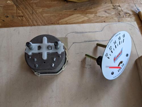 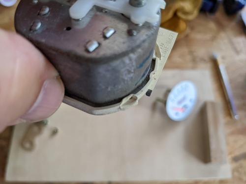 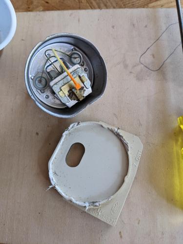 Bend all 6 of these tabs to remove the guts from the old ammeter case. On the new voltmeter, remove the screws that hold the face on. Retain the face because you'll need it later to line up with the OEM face to drill holes in the right places. 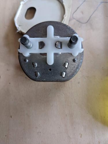 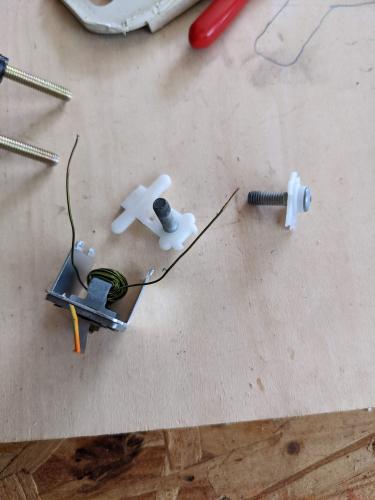 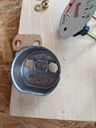 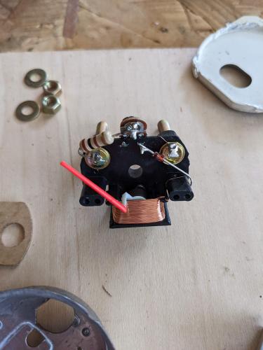 Next, you'll need to measure for the screw holes that are required to attach the OEM face to the aftermarket gauge internals. Draw a vertical line through the center indicator line of the gauge. It will follow the grid pattern lines perfectly. Then draw a line perpendicular to that as shown. I did mine exactly one grid square (from the gauge face) down from the top of the gauge needle hole, and it needed just a bit shaved off the top of the needle hole for the needle to swing perfectly. Do test fits before drawing your horizontal line. 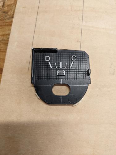 Then draw a horizontal line through the exact center of the screw holes on the aftermarket gauge face. Draw a vertical line that goes directly through the 14v indicator line. Use some scissors to trim down the aftermarket gauge face so that it will fit inside the OEM gauge face as pictured. Line up the verticals and horizontals perfectly. 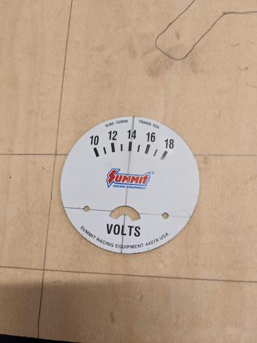 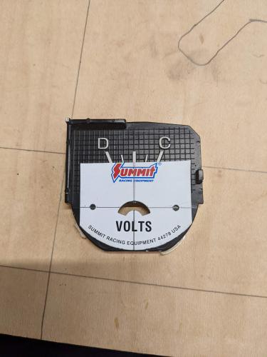 Mark the holes with a pencil. Then remove the aftermarket face and drill the places you just marked. Use a drill bit that just fits in the aftermarket face holes. Use a knife or a countersink bit to countersink the holes. I did not use the countersink bit in a drill! The plastic is soft enough that you can just spin it there by hand and remove material quickly. 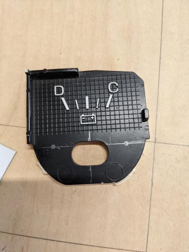 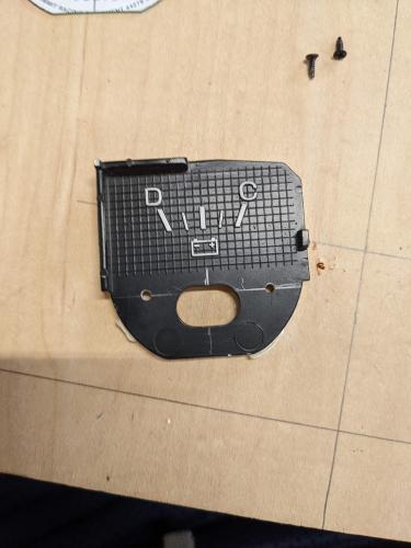 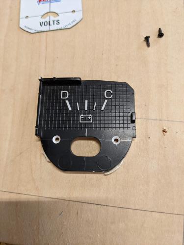 Attach the old face to the new internals. Move the needle to make sure nothing is obstructed, and fix any obstructions. I used the soldering iron to heat the bottom of the needle to bend it a bit in my case. 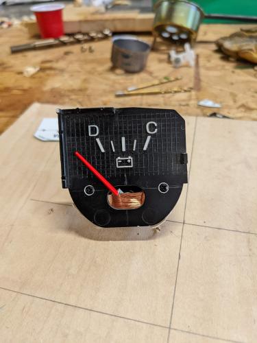 In this picture, you can see the counterweight of the needle, and that the studs are set at different widths. You also may not be able to tell from here, but the studs are the same diameter and thread pattern. 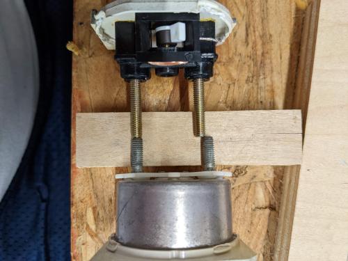 Here, you can see the PCB of the gauge cluster. Use an xacto knife to remove a bit of the PCB as shown. Use a drill bit to turn the right-hand hole (as viewed from the back of the cluster) into a slot. This was a test PCB for me. I ended up using my other PCB with the slotted plastic casing, and I did NOT need to remove any of the other PCB for this to work. So the PCB alteration is optional, but you'll have to remove it from the gauge cluster body. 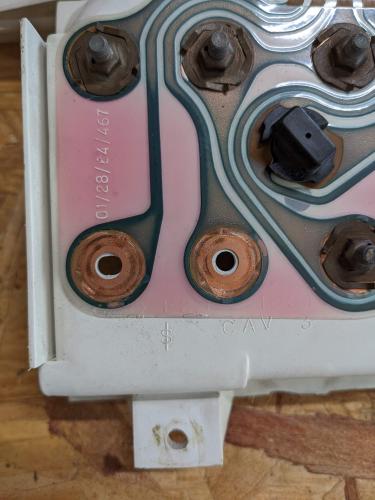  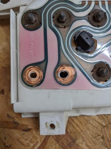 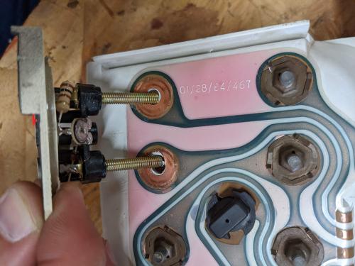 Now, to put the old gauge face onto the old gauge body again! The way the new gauge works incorporates a counterweight to the plastic needle. Because the old gauge body is flattened on the bottom, it won't let the needle swing. So you have to cut a little window out of the bottom for it to swing through. In my pictures, I made the whole bigger than it needed to be. 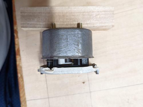 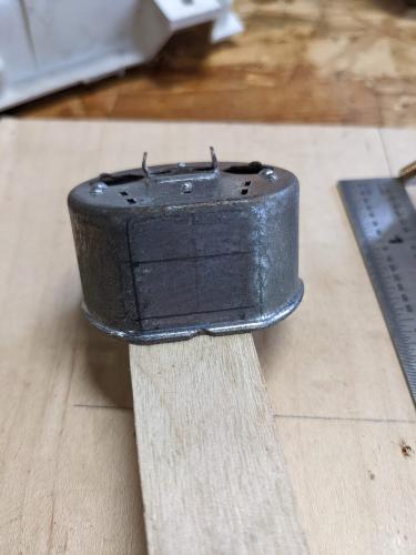 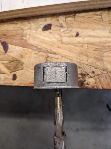 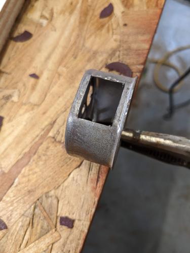 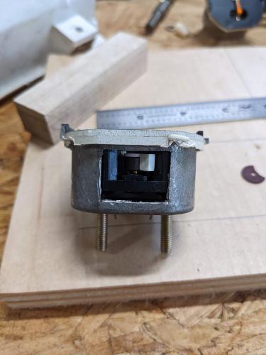 The last part you need to do to get it all to fit is to slightly widen the holes in the back with a round file. This is so the studs don't accidentally touch the body and short out. After enlarging the holes, use the OEM plastic stud girdle to keep them in place. You'll need to break or cut it for it to fit. Then superglue or epoxy it in place. 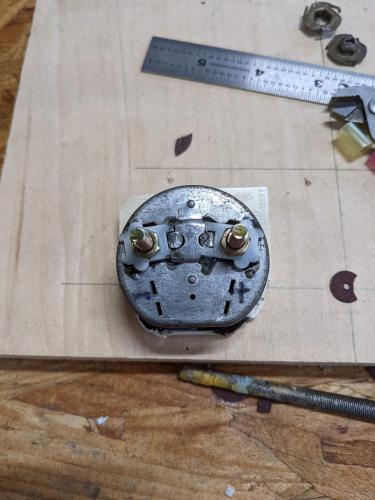 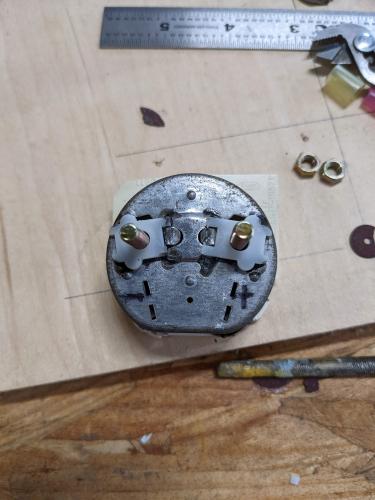 The last step is just to glue or epoxy the face and body back together. 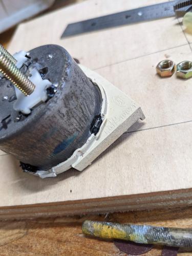 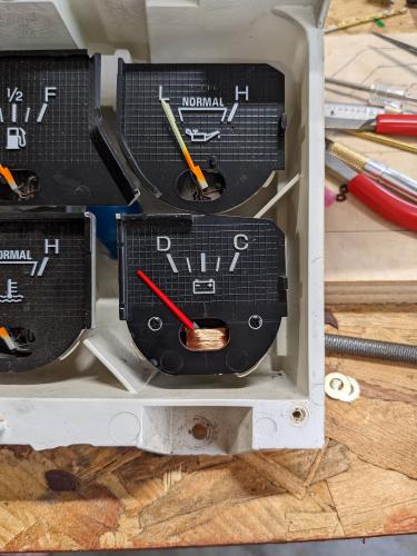 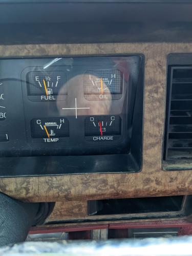 Note that this will ONLY work with the ammeter circuits removed. The wiring will need for you to locate connector C-610. The yellow/lightgreen wire will need to go to ground, and the red/orange one will need to be given hot-in-run power. It is very important that the ammeter shunt is removed for this. This page shows the wires that must be removed. https://www.garysgaragemahal.com/3g-conversion.html
1986 Bronco. 5.0L, Edelbrock Pro-flo 4 EFI, Baumann-controlled 4r70w, 3.55 gears, 31" tires.
|
Bullnose Enthusiasts Forum
› Resources & How-To's
›
How-To's
|
1 view|%1 views
| Edit this page |