3G Alternator Conversion Page Upgrade.

3G Alternator Conversion Page Upgrade.

Administrator
|
Guys - As said on another thread, I'm wanting to upgrade the 3G Alternator Conversion page. And there are at least two areas to address - what donor vehicles have the 3G's we want, and what to do about the ammeter.
So, let's start with the donor vehicles. The page says: Vehicles that are donors:
|

|
Banned User
|
This post was updated on .
The '94 service manual calls them 95A & 130A. This shows how to distinguish them quickly:
 For any alternator whose rear case isn't rotated (clocked) for your application, the rear case (with stator inside) can be separated & rotated in relation to the front (with most of the mounting points). So IDK if your donor list only includes those with the correct clocking or just all 130A 3Gs, but it SHOULD include all. For the ammeter... If it's the same as my '83's original (shunted voltmeter labelled in Amps, supplied by tiny harness wires), then no action is necessary. It may peg with the 3G's higher output, but that won't hurt THE METER or the alt. If it's an inductive ammeter (not actually connected to the wiring; just a heavy pass-through loop), that also can't be hurt by a HO alt. But I don't think Ford used that in the 80s (the '66-77 Bronco might have been the last application for that). The only type that WOULD be damaged is a full-current ammeter (heavy studs & wire) since it's not made to handle significantly more than its full range can display. But I don't think any of these trucks were built with that type. As to the factory wiring... As long as no additional loads are installed ON the factory wiring (this means the new alt, too), no additional current will flow through the factory harness, and no changes are necessary. All new or larger-than-factory loads should begin with a new fuse/fusible link from the B+ side of the starter relay, directly against the alternator output ring terminal. And they should return to the battery negative terminal, or to one of the heavy rings on that cable (frame or block). If new loads MUST be added through the factory wiring, then the alternator is irrelevant - the factory circuits MUST be analyzed & adapted for those loads. This explains the proper way to put a 3G onto a '66-77 Bronco, which is virtually identical to the installation in a bullnose:  The ignition switch is substantially different, but no connections actually need to be made there. The voltmeter can be connected to the switched circuit on the instrument cluster (Bk/LG 40, pin 1). |
Re: 3G Alternator Conversion Page Upgrade.
|
Administrator
|
Steve - Thanks for the response. But there's so much in yours that I'm going to respond in two installments.
You said "So IDK if your donor list only includes those with the correct clocking or just all 130A 3Gs, but it SHOULD include all." And if by that you mean all 130A alternators with the right mounts then I fully agree. But, I can't tell from the part numbers what the mount configuration is, and we don't want to include 130A alternators that have the different mounts. I took the original donor list and matched it up to the applications in the interchange list and found that it closely matched two different part numbers. Given that, I assumed that I had the right alternators, and proposed that list of donor vehicles. But I have no proof that those are the right two alternators. Just a good, but not perfect, overlap of applications. Are they clocked correctly? Dunno. Are there others that may be clocked differently that could be used? Dunno As said, I don't think we want to include all of the 130A alternators shown in the interchange list as there are almost certainly some in there with the wrong mounts. We can tell the reader that this list is pretty sure to have the right alternator, but that there may be other applications that use alternators that will work, and then show them the picture, again as it is already in there, of the right alternator. I think what we may need to do is to have someone spend a day at the salvage with pics of the right alternators and just write down which vehicles have them and which don't.
Gary, AKA "Gary fellow": Profile
Dad's: '81 F150 Ranger XLT 4x4: Down for restomod: Full-roller "stroked 351M" w/Trick Flow heads & intake, EEC-V SEFI/E4OD/3.50 gears w/Kevlar clutches
|
Re: 3G Alternator Conversion Page Upgrade.
|
Administrator
|
In reply to this post by Steve83
Ok Steve, now for Installment 2: The Wiring.
The Bullnose ammeters are all the same, just like your 83's. For others, since you know this, here's how the wiring looks like with the regulator and its wiring removed for simplicity. And the way it works is that any current across the shunt creates a voltage that gets registered by the "ammeter". If the current flows from left to right, which means it is flowing out of the battery, then the ammeter registers discharge. And if it flows from right to left across the shunt, meaning the battery is being charged, then that's what the ammeter registers. 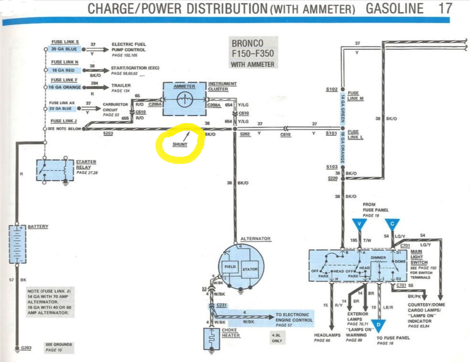 But let's assume that we replace the 1G alternator with a 130A-capable 3G and wire it the same as the factory did and have no additional electrical load in the cab. As shown below, the current to the battery will be from the ammeter through the shunt, and in normal situations all will be well. However, what if we have a dead or bad battery? The alternator will go full-tilt and with the right engine RPM's it'll kick out all 130 amps. But by my estimation that shunt is sized to handle ~70 amps, which is the largest alternators these trucks came with. I do not think that shunt will handle the load and the insulation will melt. I know that can happen because I recently helped a young man with melted wiring and he admitted he'd just replaced the alternator with a 3G - without taking the shunt out of the current's path. And I've heard of it happening to others as well. 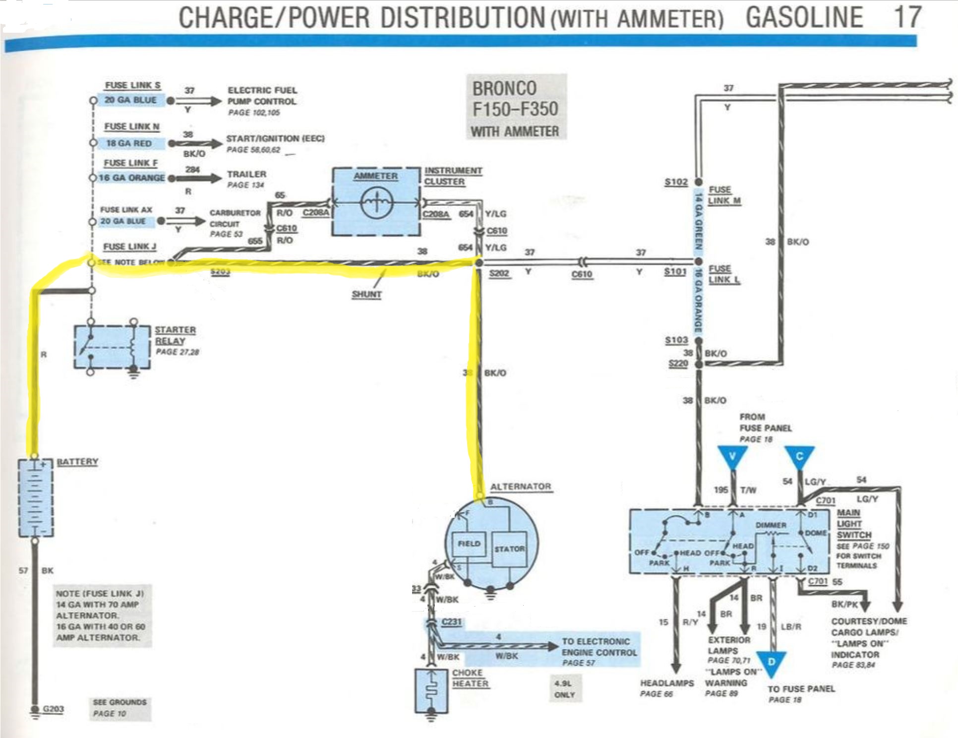 However, you suggested recently that we take the alternator's output to the relay's always-hot post. And, assuming that people do as you suggest and don't connect any additional loads to the stock wiring, that solves the problem because, as shown below, the current to charge the battery does not go through the shunt. However, whatever current is flowing to the cab will always show as a discharge on the ammeter, so if even just the engine is running there will be a slight discharge. That's not the "clean" way to do it in my opinion as I think it is better to convert the ammeter to a voltmeter, but some people don't want to bother to do that. So at least this approach will keep them from burning up their wiring. And, if you are going to turn the ammeter into a voltmeter, like I'm doing, this is the way to do it as well. The shunt won't be hurt with the current for the normal accessories, and you can use the red/orange wire as the positive lead to the voltmeter. Thoughts? 
Gary, AKA "Gary fellow": Profile
Dad's: '81 F150 Ranger XLT 4x4: Down for restomod: Full-roller "stroked 351M" w/Trick Flow heads & intake, EEC-V SEFI/E4OD/3.50 gears w/Kevlar clutches
|
|
Banned User
|
This post was updated on .
That's why, in my first reply, I mentioned that a higher-than-factory alt counts as "additional load". It surprises me that anyone would try or even THINK that the old Bk/Or wire would be a good place to connect a 3G, if they saw the 3G's original output wire (presumably while removing the 3G at the JY). And as easy as it is to pull a 3G harness (1 starter relay nut & 1 easy connector on the LG/R wire), I really can't imagine any easier or more-obvious way to do the swap. That's a separate issue from the alternator wiring, and the wiring for additional loads. A voltmeter is neither a significant new load, nor a requirement for a 3G to work. But I recommended the voltmeter in my first reply. I'm not sure which approach, and which way to do it you mean there. The approach in your diagram above; the way in your diagram below; or were you still referring to my post? That's not correct. The factory ammeter wires are always hot. The voltmeter should be switched, as I described in my first reply. It's very easy to solder a new wire to the ICVR's brass button on the film circuit. Just be sure to put it on the INPUT side (steady 12V). For convenience, the voltmeter negative can go to the ICVR's mounting/grounding screw. |
|
Administrator
|
In reply to this post by Gary Lewis
Gary, I would consider myself more of a consumer of this page than a contributor, as I have not actually done a 3G swap, and I would definitely need help getting it wired in correctly. That said, I can give my input regarding what I think would be useful.
When you walk out onto the pick ‘n pull lot, it is probably going to take you more time to verify the model year and engine of the car than to just check the alternator and see if it is the right type. Not that a comprehensive list isn’t useful, but the bottom line is to be able to ID the alternator. If I went hunting I would probably poke my nose under the hood of all large-ish 90’s Ford’s and what I would need would be clear photos showing what I want and don’t want and how to tell them apart. Where you want/need an exact year, model, and engine size is if you choose to order an alternator online or through a parts house. In that case, you do need the correct application details. But ONE correct application is enough. Regarding the ammeter issue, I think folks just need to realize that ~something needs to be done, and what the options are (even if it’s just to disconnect it to prevent meltdown). Having pulled quite a few instrument clusters, I can say that several have had burnt circuit films going to the ammeter. I can’t really speculate what the cause is (with a stock alternator) but this is one more argument in favor of switching to a volt meter or aftermarket ammeter that does not use the stock gauge wiring. The other thing that I believe would help folks is a reference to convert a 3G to V belts. Maybe it is only the IDI, but I remember reading that you needed to find a pulley with the right amount of offset, and that was from some odd Dodge application. I will try to dig that up, vague though it was. Do you know if that is the case with the gas engines? Or can you remove and use the 1G or 2G pulley if you are running V belts?
SHORT BED 4-DOOR DIESEL: 1986 F350 4x4 under construction-- 7.3 IDIT ZF5+GVOD
STRAIGHT SIX 4X4: 1981 F150 2wd to 4x4-- 300 I6 close ratio diesel T19, hydroboost brakes, Saginaw steering BIG F: 1995 F-Superduty under construction— converting to 6.9L IDI diesel ZF5+DNE2 |
Re: 3G Alternator Conversion Page Upgrade.
|
Administrator
|
In reply to this post by Steve83
I was asked to throw my $.02 into this discussion. Biggest issue I saw in doing mine, in addition to the pulley issue with V-belts. The shunt for the ammeter is a limiting factor as Steve points out. In order to get the voltage drop (which is what the "ammeter" is measuring) the shunt is sized to provide a good deflection at maximum load in either direction. I actually talked to an electrical engineer trying to come up with a decent solution, which basically boiled down to "if you increase the shunt size you loose sensitivity to smaller loads". This means a small discharge condition may no be immediately evident.
That being said, his recommendation was to simply bypass the shunt and add a voltmeter to the truck. The voltmeter conversion, provided it is wired for key on only operation is a great modification, good enough that Ford did it staring in 1987. Ammeters were a valuable indicator in the days of 25-35 amp generators and were frequently always hot meaning the generator (or alternator on Chrysler products) was in series with the load and output. Power from the generator went through the ammeter then to the electrical loads so a discharge actually meant you were running on the battery as the generator output was too low, charge meant the generator was providing more current then what was needed for the loads and was charging the battery. Side note, my first truck, a 1958 F100, had a 25 amp Ford generator. It originally just had two idiot lights and a temperature and gas gauge. I scored an instrument cluster from an F600 in a junk yard with full gauges and installed it. Winter driving, after a week of in town, if I didn't get on the interstate and drive it a good ways, midway through the second week, it would get very slow to crank.
Bill AKA "LOBO" Profile
"Getting old is inevitable, growing up is optional" Darth Vader 1986 F350 460 converted to MAF/SEFI, E4OD 12X3 1/2 rear brakes, traction loc 3:55 gear, 160 amp 3G alternator Wife's 2011 Flex Limited Daily Driver 2009 Flex Limited with factory tow package Project car 1986 Chrysler LeBaron convertible 2.2L Turbo II, modified A413 |
Re: 3G Alternator Conversion Page Upgrade.
|
Administrator
|
Ok, I think we now have enough varying views that we can sorta pull things together. Let me address a few things from what each of you have said, but I'm sure I'll miss some of your favorite points:
Steve - I have seen people wire a 130A alternator to the existing alternator lead, so I think it is important that we tell them not to do that, and why. As for using the red/orange wire to run the voltmeter, I want to use that for two reasons. First, because I want to know the battery voltage and not the voltage in the cab. The wiring to the cab is, in my opinion, less than adequate, and coupled with marginal switches and varying current loads, causes the voltage in the cab to vary significantly. So I want to know what the battery is "seeing". Big Blue's aftermarket voltmeter was wired to the fuse block when I got him and it always read low enough to cause concern on my part. Second, using that wire means I don't have to run another wire to the voltmeter. But, I think you misunderstood my intent, which was to install a key-on relay in that wire - although I didn't say that. Or, maybe put a key-on relay in the dash to provide the ground to the voltmeter? You have to be in there changing the ground side of the gauge anyway, so..... Also, I wouldn't want to use power from the ICVR. There is an "8 to 9 ohm" resistance in the feed to the ICVR (see Pg 98), and since the gauges can pull about an amp each that would cause a significant voltage drop. But I think overall we are in agreement. Jonathan - As we've discussed on the side, the current page does have some pics of the alternators as well as a discussion of the pulleys. But you've volunteered to get more of pictures when you are able to get to the salvage, which we can certainly use. And if you find the discussion of the IDI pulley issue we can take that into account. Bill - I went through exactly the same thinking as your engineer friend regarding replacing the current (pun intended) shunt and came to the same conclusion. Any shunt that would give the same voltage drop across it as the current shunt but with twice the alternator output wouldn't show anything noticeable if the alternator died and you just had a few accessories on. I even explored using a Schottky diode in parallel to the shunt to carry the charging load but allow the shunt to work in the discharge direction. But the voltage drop across the diodes isn't linear so that wouldn't work. However, having another shunt in series with the diode and having that combo in parallel with the original shunt would work. But it was too complex and I finally decided the voltmeter would be easier and better. All - Let me work on the page and get back with you. Unfortunately I'll actually have to either modify the current (  ) page or, maybe duplicate it and hide the test one, as I can't really show you my plans here in this thread. Thanks for the help. ) page or, maybe duplicate it and hide the test one, as I can't really show you my plans here in this thread. Thanks for the help. 
Gary, AKA "Gary fellow": Profile
Dad's: '81 F150 Ranger XLT 4x4: Down for restomod: Full-roller "stroked 351M" w/Trick Flow heads & intake, EEC-V SEFI/E4OD/3.50 gears w/Kevlar clutches
|
|
Banned User
|
But then you're talking about using the factory wiring to the cab - the ammeter wiring. No matter what wiring you use, you're always getting voltage "in the cab" if that's where the gauge is. So why not just run the wiring the way it needs to be? You have to run 2 wires to the voltmeter no matter what - it's not going to attach to the film circuit. So it's not "another" wire to the voltmeter - it's just one of the 2 that are required. And they don't have to be big - telephone wire is big enough (if anyone remembers what THAT is!  ). ).It doesn't matter which side of the voltmeter is switched - every additional connection & switch in the circuit adds resistance. But the ig.sw. is self-cleaning, and built to handle a lot of current. So it's the best switch to turn the voltmeter on. If there's resistance in the stock wiring, fix that. Adding more wiring to bypass problems is just adding more problems. There's at least one BIG error in that diagram, so that resistor might be another. Haynes doesn't show it, and I can't imagine why it would be there, in addition to the ICVR. I don't recall my truck having it. I'm not sure where you're getting those numbers, but that would mean each gauge averages 5 Ohms, which seems VERY low to me. Especially considering that the fuel sender alone can't go below ~20 Ohms. At 5V, that would limit its max current (even if the gauge had 0 Ohms) to 0.25 Ohms. My point is: you're in there "fixing" the wiring anyway - why not do it right and fix it all? Don't work around other problems just because they're common & not directly-related to this swap. |
Re: 3G Alternator Conversion Page Upgrade.
|
Administrator
|
First, for reference I'm quoting info from this page (Electrical/Gauges) and the Gauge Circuits & Spec's tab, which shows the results of my testing of the gauges and wiring harness, and refers to the ICVR page with discusses my testing of that monstrosity.
 Some time ago I got tired of doing tests and then losing the results, so have been documenting my testing for posterity. Some time ago I got tired of doing tests and then losing the results, so have been documenting my testing for posterity.
Depending your definition, yes it could be considered the voltage "in the cab", but it will be measuring the voltage effectively at the battery since the red/orange wire connects essentially to the hot terminal of the starter relay. And, my testing shows that the ammeter Rocketman converted to a voltmeter for me only pulls ~80 ma, so there will effectively be no voltage drop on that wire to the ammeter since there is nothing else on that wire. In other words, it will be reading battery voltage. Having said that, 80 ma is too much current to be pulling all the time, so I agree that a relay is required. And for that I'm considering placing a relay in/under the dash to switch the ground to the voltmeter. And, I may take the pull-in current from the black/light green wire which is going to the hot side of the ICVR - as you suggested.  I really don't have to run any wires to the voltmeter. As said, the red/orange wire will bring battery voltage right through the film circuit to the voltmeter. And I'll break into the yellow/light green wire in the harness prior to the connector to the cluster and install the relay and ground circuit, so the yellow/light green wire will bring ground to the voltmeter, right through the film. That way there's no change to the cluster itself but installing the voltmeter. As said, there's so little current being pulled for the voltmeter that the skinny little red/orange wire won't have enough voltage drop to worry about. And there are no switches nor other wires to go through but the relay and its ground. That resistor is there, as you can see on the Gauges page. My DVM registered 8.9 ohms, which is what the all the EVTM's show as well as both the '85 and '86 Wiring Diagrams show at D13 on Page 1. Well, my numbers for current draw were off.  As you can see from the Gauges page, each gauge pulls about .2 amp, not the 1 amp I was remembering. But the fuel senders run from 10 ohms to 73 ohms, also shown on the Gauges page. And the gauges run about 12 ohms themselves. As you can see from the Gauges page, each gauge pulls about .2 amp, not the 1 amp I was remembering. But the fuel senders run from 10 ohms to 73 ohms, also shown on the Gauges page. And the gauges run about 12 ohms themselves.
I think I am fixing the wiring correctly, but that's my opinion and not everyone will agree with me. I plan to use the factory's hot wire to the gauge and switch the ground with a relay triggered by key'd power. No wires to run through the firewall and nothing to change other than the ammeter to a voltmeter and the ground circuit. Ok, all of that is really about how I want to put a voltmeter in the system. But now let's turn to the 3G page "upgrades". I've duplicated the existing page and have hidden it in the menu - two ways: 3G Alternator Conversion - Tabbed: I'm thinking that there is too much info to put it on one looooong page, so am playing with it in a tabbed format.3G Alternator Conversion - Test: To this point this version is just an edit of the loooong page format.So, I'd like everyone's input as to which approach seems best - tabbed or loooong paaaaaggggeeee.  I'll work in the background as I can to "upgrade" what is one of our most popular pages on the website. Let's see if we can't make it a bit better.
Gary, AKA "Gary fellow": Profile
Dad's: '81 F150 Ranger XLT 4x4: Down for restomod: Full-roller "stroked 351M" w/Trick Flow heads & intake, EEC-V SEFI/E4OD/3.50 gears w/Kevlar clutches
|
|
Administrator
|
This post was updated on .
Gary, I was not able to find the reference regarding the Dodge pulley that some use for 3G conversions to eliminate having to use the spacer. I did find a post on FTE that said it was larger in diameter than the stock pulley and there was some concern that it might not spin fast enough.
What is interesting is that 1992 Ford Econoline vans with the 7.3 IDI came with a 130A 3G alternator and a 2 groove V belt pulley. If you order that alternator it will have the right pulley straight out of the box with no shim or pulley swap needed. Of course, like all convenient parts solutions, this one may be going the way of the dodo. The eBay listing says out of stock, Summit webpage says not available, and RockAuto says only 1 remaining. Other online sellers have it listed, but I don’t know how long this will be an option. I’m almost tempted to buy one just so I have that pulley to put on future units if/when the inventory of ‘92 diesel van alternators dries up. 😔 The manufacturer part number is 7756-3N-2G. This website gives a couple of Ford part numbers for it: https://www.obbstartersandalternators.com/ford-alternator-7756-f2uu-10300-f2uz-10346-f2uz-10346-f2uu-7756-p-3521.html?gclid=EAIaIQobChMIt4i2mOGr4AIViLfACh0qigUTEAQYASABEgLE6_D_BwE Here is the image from the out of stock eBay listing: 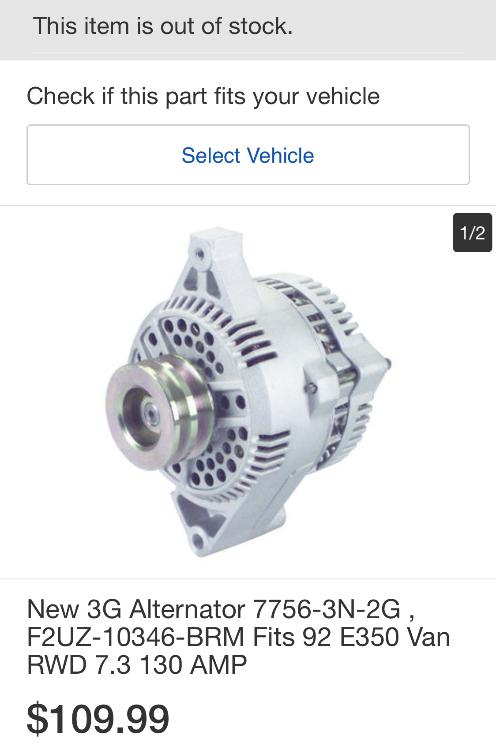
SHORT BED 4-DOOR DIESEL: 1986 F350 4x4 under construction-- 7.3 IDIT ZF5+GVOD
STRAIGHT SIX 4X4: 1981 F150 2wd to 4x4-- 300 I6 close ratio diesel T19, hydroboost brakes, Saginaw steering BIG F: 1995 F-Superduty under construction— converting to 6.9L IDI diesel ZF5+DNE2 |
Re: 3G Alternator Conversion Page Upgrade.
|
Administrator
|
As far as the spin speed on the upgraded alternators, when I did Darth, I had already mounted the poly-groove belt system and once I did the EFI conversion, I eliminated the unneeded Thermactor pump (it only feeds the catalytic converter on the EFI 7.5L). I had an issue with the pulley that came with the conversion kit being so small the belt would slip on initial start up when the alternator was under a good load. I ended up getting a pulley off a Taurus 3.8L which is about the same OD as the V-belt one on the carbureted 7.5L, no more problems, it didn't actually squeal, just failed easily and left rubber dust all over the alternator.
FWIW, Darth came with a whopping 60 amp 2G for a crew cab DRW truck with 7.5L, and loaded including the trailer package, go figure?
Bill AKA "LOBO" Profile
"Getting old is inevitable, growing up is optional" Darth Vader 1986 F350 460 converted to MAF/SEFI, E4OD 12X3 1/2 rear brakes, traction loc 3:55 gear, 160 amp 3G alternator Wife's 2011 Flex Limited Daily Driver 2009 Flex Limited with factory tow package Project car 1986 Chrysler LeBaron convertible 2.2L Turbo II, modified A413 |
Re: 3G Alternator Conversion Page Upgrade.
|
Administrator
|
Thanks guys.
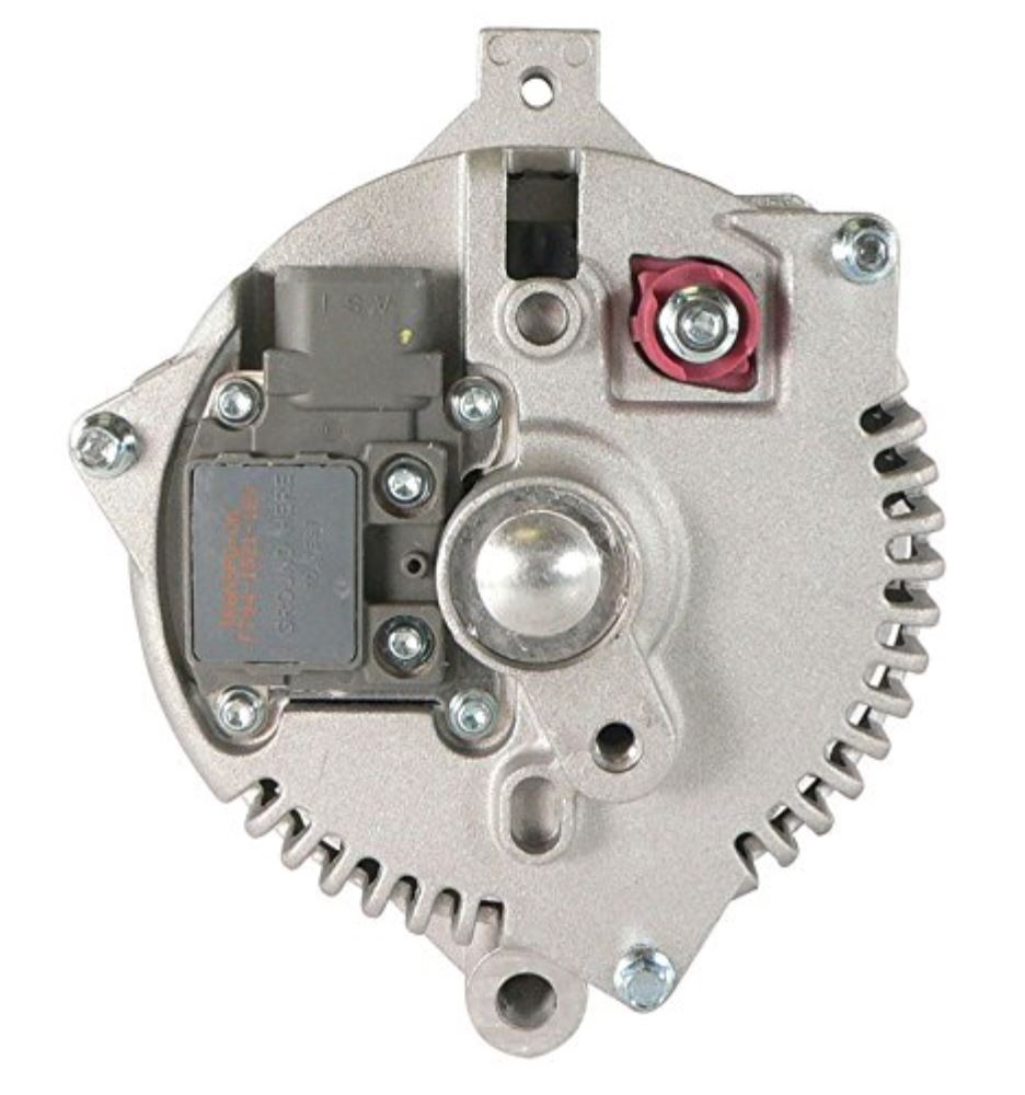
Jonathan - Your link is interesting for several reasons. And one of those is the "Clock: 3:00". I was Googling the part numbers we have last night and came across some listings from DB Electrical, more of which later, and found one that says "Clock: 11". So, see the pics down below, with the 11:00 o'clock pic on the left and the 3:00 o'clock pic on the right. Looks to me like the "clocking" references the position of the plug, and the position of the alternator for that determination is with the pivot ear down and the clamp ear up. Now for the DB Electric alternators I found: F4PU-10346-BA: This is the one that fits Mustangs, T-Birds, and Cougars. Notice that it is only $82.83 with a 1-year warranty and has a 6-GROOVE PULLEY 64mm OD.F1DZ-10346-A: Note that this one isn't the other part # we'd found as it ends with "-A" instead of "-B". But it does fit those applications, and then some. And, maybe more importantly, it is a 200A unit, and the description says "Under full load conditions, amperage output at 1200 engine rpm will peak at 200 Amps, amperage output at 600 engine rpm (idle) will peak at 100 Amps." But, it does cost $235. |

|
Banned User
|
In reply to this post by Gary Lewis
Aha! Then I suggest mentioning that extra mod on the 3G page, but focusing on the more-common/cheaper/easier/quicker method of installing an aftermarket voltmeter (or '87-04). Then put the full writeup of the modded ammeter & its wiring on your personal build page. That's what I meant: a terminal on the wire; to connect to the terminal on the relay; that goes to one of the contacts; going to the other contact; leading back to a relay terminal; mated to another wire terminal. All of those connections will be in your "true battery voltage" circuit. To me, that seems like a lot more work & risk than just finding the 8.9 Ohm resistor, and bypassing it. I might even cut the R/Or wire, and splice it into the Bk/LG on the B+ side of that resistor. |
Re: 3G Alternator Conversion Page Upgrade.
|
Administrator
|
Steve - I'll see how I can incorporate the voltmeter options into the 3G page.
But, I don't think it is wise to remove the 8-9 ohm resistance. (It looks to be a piece of resistance wire as I can't detect any bulges in the run.) I believe it is there to drop the voltage to the flasher/ICVR and thence to the gauges. So unless the user is replacing the ICVR w/a real regulator, removing the resistance will change the average voltage to the gauges and, therefore, change the current, causing the gauges to read incorrectly. All - I called DB Electric and talked with a really nice lady named Christina. Told her what I'm looking for and she said I need to talk to Hagan, who is in his 70's and really knows this stuff. Since I'm almost 72 we should get along famously but, since he's out today, I'm to call him early Monday. And, I'd like to brainstorm the questions to ask him. Here's my current thinking: Is there a name for the style of mount we need? Or a range of part #'s?How much power can the various pulley types transfer? (We should help the reader understand that a single v-belt is limited to something like 90A w/o slipping, and many people who've converted to a 3G have experienced significant belt squeal.)If people want to order an alternator with a specific pulley how would we determine the needed part number? And do they have pulleys for two v-belts of the same size. (I'm thinking of Jonathan's recent post.) Is there a way we can create a table with their part #'s and the various pulley styles and sizes?What about regulators? Which of their alternators have slow-start or LDR regulators in them? (Slow, or delayed-start regulators bring the alternator in slowly to prevent the belt slippage that Bill spoke of.)Is there a disadvantage, other than cost, for the high-output units? Do they put out a higher percentage of their rating at idle than the standard 130 amp units?So, what questions do y'all have?
Gary, AKA "Gary fellow": Profile
Dad's: '81 F150 Ranger XLT 4x4: Down for restomod: Full-roller "stroked 351M" w/Trick Flow heads & intake, EEC-V SEFI/E4OD/3.50 gears w/Kevlar clutches
|
Re: 3G Alternator Conversion Page Upgrade.
|
Administrator
|
LRC (load response control) regulators were found on Lincoln's and other luxe barges because of things like heated and auto adjusting seats.
I never saw a 3G with a V-belt pulley. I always called it a pivot mount. With 7 or 8.25" c-c spread. Other styles include side mount and V-mount. Belt squeal has always been an issue. Ok, that's my 2c.
Jim,
Lil'Red is a '87 F250 HD, 4.10's, 1356 4x4, Zf-5, 3G, PMGR, Saginaw PS, desmogged with a Holley 80508 and Performer intake. Too much other stuff to mention. |
|
Banned User
|
This post was updated on .
In reply to this post by Gary Lewis
I don't think it's necessary, but I didn't say to remove it - just bypass it ONLY for the voltmeter feed. It would still be there for the ICVR feed. It's not that simple. You also have to consider wrap angle & pulley diameter to know how much torque the belt can apply to the alt before it slips. According to Ford's graphs, there's no appreciable difference.  There's no reason to install a 95A 3G on anything. As to higher-than-stock-output 3Gs; I just don't trust them enough to risk that kind of money on something that isn't warranted locally. 130A is plenty - especially for a truck originally built to use 70A. |
Re: 3G Alternator Conversion Page Upgrade.
|
Administrator
|
In reply to this post by ArdWrknTrk
Jim - Jonathan was just talking this morning about the '92 vans with the 7.3 IDI having a 3G w/a 2-sheave pulley. So apparently they existed but are in short supply. I hope DB says they can do one as I think Jonathan wants one, and it would make things easier for others as well.
 Yep, LRC is the right term. I'd forgotten. But, I'll ask Hagan about it on Monday. To me that would be the way to go and I added that to the revised page, although depending on what he says that may need to change. But it seems like it would help w/the belt squeal. Steve - Yes, the power transfer depends on tension, belt-wrap, etc. So maybe I should edit the page to say that 90 or 100A is the max you can get with the proper belt-wrap, tension, etc. But, let's see what Hagan says about it. As for more power at idle, not all of the alternators people will be dealing with will be stock Motorcrafts. DB's 200A unit says "Under full load conditions, amperage output at 1200 engine rpm will peak at 200 Amps, amperage output at 600 engine rpm (idle) will peak at 100 Amps". So that's why I'm asking that question - do all of their alternators put out 50% of their rated output at idle? Or is it just the HO ones? And on the 90/95A unit, I've wondered that as well. I could simplify things by just taking the discussion of them out. As for the 220A units, the longevity thereof is probably a good question for Hagan. All - I've got a DRAFT of the revised page that I really, REALLY need you to read and comment on: Tabs: No one said boo, so I chose the layout I like - tabs. |

Re: 3G Alternator Conversion Page Upgrade.
|
Administrator
|
Gary,
A) I don't think the idi has a pivot mount. Iirc it is a 2 bolt side mounted alternator. Pulley alignment (belts in plane) seems the most important criteria. So check the offset, shoulder to belt centerlines before committing to the idi pulley. Sourcing a crank pulley with two sheaves the same size might be a challenge too. B) Ryan had graphs of the regular 130 putting out over 65 Amps at engine idle rpm, whatever the pulley ratio caused the alternator to spin. (so more at idle than a 2G was rated for outright, but exactly 1/2) Good of you to make that distinction, and observation. C) The "overclocked" alternators should have more robust diodes and heavier copper heatsinks on their rectifier board. The smaller case of the 95A alternators just doesn't provide enough cooling. (Fan flow and/or heatsink) I'm aware of the size and pulley width of the Mitsubishi 200+A ambulance alternator. I doubt any 3G case size unit could do that for long, even if it was chain driven.
Jim,
Lil'Red is a '87 F250 HD, 4.10's, 1356 4x4, Zf-5, 3G, PMGR, Saginaw PS, desmogged with a Holley 80508 and Performer intake. Too much other stuff to mention. |
|
|
I have a 130 A 3G alternator on my truck with a single V-belt and so far (fingers crossed) it is not slipping.
God Bless
Whisler Frankenstein: 1989 F250 4X4, C-6, Hurst Pro-Matic 2 shifter, carbed '84 351W, Edelbrock manifold, Edlbrock AVS, DS2 ignition, 3G alternator, JBA shorty headers, no cats, dual exhaust with H pipe. |
| Edit this page |